STEREO SOURCE SELECTOR/PREAMPLIFIER OPERATION MANUAL Version - 1 April 2000
CONTENTS Page 1. Introduction 3 2. Installation 4 2.1 2.2 2.3 2.4 2.5 2.6 Inspection and un-packing Operating environment CE standards Power requirements Signal levels External connections 4 4 4 4 5 6-7 3. Warranty 8 4. Description of controls 9-10 4.1 4.2 4.3 Inputs section Outputs section Headphones section 9 10 10 5. Applications 11 5.1 Using the SPX20 6. Circuit description 13 7.
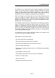
1.0 INTRODUCTION The SPX20 is a six input stereo source selector designed to extend the number of inputs and range of monitoring facilities available on a typical mixing console. However the SPX20 is suitable for a wide range of monitoring applications including tape dubbing, audio-visual and digital workstations and for installation in background music applications.
2.0 INSTALLATION IMPORTANT: PLEASE READ THIS SECTION BEFORE USING THE SPX20 2.1 INSPECTION AND UNPACKING The SPX20 has been carefully packed at our factory in a carton designed to withstand handling in transit. Should the unit appear to have been damaged in transit notify your dealer immediately and do not discard any of the packing. The carton should contain • The SPX20 unit • Power cord • Operator Manual (this book) 2.
• Please check that your unit is correctly rated for the voltage in the country of operation. If the fuse requires changing at any time please ensure the correct fuse is fitted. An incorrect fuse could cause damage to the unit and may constitute a fire hazard. If you carry your SPX20 from one country to another it is very important to ensure the voltage is compatible. For your information the unit can be internally rewired for use in 230V, or 115V and 100V countries - contact your dealer for information.
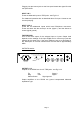
PUSH Pin 2 = Hot (+) Pin 1 = Screen Pin 3 = Cold (-) Fig 2.6.3: Pin arrangement for XLR inputs on the SPX20 Pin 1 Pin 2 Pin 3 Screen Hot Cold Signal ground Signal + Signal - For unbalanced operation join pins 1 and 3 and connect to Screen (signal ground) and use pin 2 as Hot (signal +). Input 1 also has a pair of front panel inserts on TRS jacks which are wired as follows - Sleeve Screen Ring Cold (-) Tip Hot (+) Fig 2.6.
Plugging into the inserts jacks on the front panel breaks the signal from the rear panel XLRs INPUT 2 & 3 These are balanced inputs on TRS jacks - see Fig 2.6.3 For ubalanced operation wire as described above for Input 1 inserts or use a mono jack plug. INPUT 4,5 & 6 These are all unbalanced inputs which have RCA/phono connectors. These are wired with the centre pin as hot (signal +) and the sleeve as screen (signal ground). TAPE RECORD This is line level output of the selected input or inputs.
3.0 WARRANTY Your LA Audio SPX20 has been manufactured to a high standard using quality components. If correctly installed and operated the unit should give years of problem free operation. However in the event of a defect in material or workmanship causing failure of the unit within one year of the date of original purchase we will agree to repair, or at our discretion replace, any defective item without charge for labour or parts.
4.0 DESCRIPTION OF CONTROLS 4.1 INPUTS SECTION INPUT 1 Left & Right sockets These are insert points for Input 1. Plugging into these connectors breaks the signal from Input 1's rear panel XLRs. They are intended to allow a quick and easy way of temporarily connecting an external piece of equipment to the SPX20. TRIM control The TRIM control for Input 1 has a range of ±10dB which should provide adequate adjustment for levels provided by pro, semi-pro and commercial equipment.
4.2 OUTPUT SECTION BALANCE control This control allows adjustment of the stereo centre position. The centre detent position gives equal left and right levels. Turning BALANCE fully CCW cancels all right output signals and vice versa. BALANCE affects OUTPUT 1 & 2 and Headphones. DIM switch Pressing this switch in reduces output levels by 20dB. DIM affects OUTPUT 1 & 2 and Headphones. MONO switch Pressing the MONO switch sums left and right signals. MONO affects OUTPUT 1 & 2 and Headphones.
5.0 APPLICATIONS The majority of mixing consoles, even quite expensive models offer only 2 or possibly 3 monitoring inputs. So if you want to simultaneously connect a CD player, DAT machine, stereo cassette deck, 2 track analogue tape machine etc. you will have to use up input channels. These are often already used for tape returns or for FX so some repatching and gain adjustment will necessary in order to replay these sources.
Fig 5.1.1 Connecting the SPX20 as the main monitoring controller 5.2 AS A MONITOR EXTENDER If you prefer to keep control of the control room monitors within the mixing console the SPX20 can be connected as shown in Fig 5.1.2. The SPX20 is now selected by pressing the 2T (2 track) return on the monitor section of the mixing console. CD 2T INPUT DAT MONITOR OUTPUT Mixing console Cassette 2 track Power amp INPUTS OUTPUT SPX20 Stereo source selector Fig 5.2.
6.
7.0 SPECIFICATIONS INPUTS 1 2&3 4, 5 & 6 electronically balanced, 20kΩ, XLR-F, pin 2 = hot electronically balanced, 20kΩ, 1/4" TRS, Tip = hot unbalanced, 20kΩ, RCA/Phono, Centre pin = hot OUTPUTS TAPE RECORD 100R, RCA/Phono, Centre pin = hot OUTPUT 1 & 2 Type 1/4" TRS jack Impedance Max. output Ground sensing, balanced impedance 0dBu (nominal), wired Tip = hot <100Ω +20dBu PERFORMANCE THD+N < 0.015% Noise <-90dBu, 20Hz to 20kHz Frequency response +0, -0.