4 Channel Frequency Conscious Noise Gate Operation Manual June 2005
This page has been left intentionally blank for your notes Page 2
CONTENTS 4 1.0 OVERVIEW 2.0 2.1 2.2 2.3 2.4 2.5 2.6 2.7 2.8 2.9 2.10 2.11 DESCRIPTION OF CONTROLS Bypass switch and led Listen switch Hi-Pass control Lo-Pass control Ext. Key led Threshold control Above-Below leds Attack switch Range switch Release control Link switch 5-7 3.0 3.1 3.2 3.3 3.4 3.5 3.6 EXTERNAL CONNECTIONS Side Chain insert Input Output Level switch Power switch Power inlet 8-9 4.0 4.1 4.2 4.3 4.
1.0 OVERVIEW Main Features: • • • • • • • • • 4 channels of Frequency Conscious Noise Gating Variable Hi and Low Pass side chain Filters Fully variable Threshold and Release Fast and Slow Attack modes Range switching between -20dB and -80dB Side chain Listen facility Stereo linking Side chain inserts Balanced Inputs-Outputs with +4dBu/10dBV switching The G400 is a professional 4 channel noise gate that can be operated as 4 separate processors or linked as two independant stereo pairs.
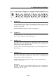
2.0 DESCRIPTION OF CONTROLS 2.1 BYPASS switch Pressing BYPASS cancels gating by removing the side chain voltage from the voltage controlled amplifier (VCA). The Input-Output and level change circuitry remain in the signal path. The BYPASS led lights when the compressor is Bypassed. 2.2 LISTEN switch This facility allows the side chain signal to be monitored at the channel output. This is useful for tuning the side chain filters by ear. 2.
2.5 EXT. KEY led EXT. KEY lights when a jack is plugged into the side chain insert on the rear of the G400. 2.6 THRESHOLD control THRESHOLD sets the reference level at which the gate will open and allow audio through to the output. Control range is -50dBu to +20dB. The side chain on the G400 has been designed with 'auto-level-sensing' and Hold circuitry to ensure that both fast transient and low frequency signals operate the gate without false triggering and/or chatter.
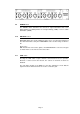
2.9 RANGE switch The RANGE switch determines the amount of signal attenuation that occurs during gating. The G400 provides for full signal muting (-80dB) or a more subtle attenuation (-20dB). 2.10 RELEASE control RELEASE adjusts the speed at which the gates closes once the input signal level has fallen below that set by the THRESHOLD control. Control range is 10mS to 4S. Please note: With instruments such as bass guitars, short RELEASE times can cause the gate to chatter.
3.0 EXTERNAL CONNECTIONS 3.1 SIDECHAIN The Side chain TRS jack allows connection of an external processor such as a parametric equaliser for more sophisticated frequency conscious gating applications. External key signals are often used for gated-reverb, rhythmic and bass enhancement effects. This is an unbalanced insert with Ring wired as Send and Tip wired as Return.
The Side Chain insert operates at -2dBu in both +4dBu and -10dBV modes. 3.5 POWER Mains power switch for G400 3.6 POWER INLET Standard IEC mains inlet for use with a detachable mains cable. See Section 3.4 for details of power requirements and fusing. Please note: The mains protection fuse is inside the unit, accessed by removing the top cover. Ensure that the unit is disconnected from the mains supply before attempting to replace the fuse.
4.0 4.1 INSTALLATION INSPECTION AND UNPACKING The G400 has been carefully packed at our factory in a carton designed to withstand handling in transit. Should the unit appear to have been damaged in transit, notify your dealer immediately and do not discard any of the packing. The carton should contain • The G400 • Power cord - country specific, please check • Operator Manual (this book) 4.
Please note: If the fuse requires changing at any time please ensure the correct type is fitted. An incorrect fuse could cause damage to the unit and may constitute a fire hazard. The detachable IEC mains lead connections to the appliance are coloured in accordance with the following code: Green-and-Yellow Blue Brown Earth Neutral Live WARNING: THIS APPLIANCE MUST BE EARTHED Please note: A protective earth connection, made by way of the earth conductor in the power cord, is essential for safe operation.
5.0 WARRANTY Your LA Audio G400 has been manufactured to a high standard using quality components. If correctly installed and operated the unit should give years of problem free operation. However in the event of a defect in material or workmanship causing failure of the unit within 1 year of the date of original purchase we will agree to repair, or at our discretion replace, any defective item without charge for labour or parts.
6.0 TECHNICAL SPECIFICATIONS ELECTRICAL Frequency response: Input Impedance: Maximum Input Level: Input-Output Level: 20Hz to 20kHz (+0, -0.5dB) 20k balanced +20dBu +4dBu or -10dBV Output Impedance: Max. Output Level: 100R balanced +20dBu THD: Signal to Noise Ratio: < 0.
7.0 DIMENSIONS In keeping with our policy of continuous improvement LA Audio reserves the right to alter specifications without prior notice. Manufactured in the UK by LA Audio Web: www.laaudio.co.uk.