AlberTine 36 Dual Fuel Range AlberTine AlberTine User Guide & Installation & Service Instructions U109956-07
Contents 1. Important Safety Information 1 2. Range Overview 5 3. Multi-function Oven cooking guide 12 4. Cleaning Your Range 14 5. Troubleshooting 16 6. Installation 19 7. Conversion to LP Gas 34 8. Service and Parts 38 9. Circuit Diagram 39 10. Technical Data 40 11.
1. Important Safety Information Have your appliance properly installed and grounded by a qualified technician in accordance with the National Electrical Code ANSI/NFPA No. 70 – latest edition, and local code requirements. In Canada, electrical grounding must be in accordance with the current CSA C22.1 Canadian Electrical Code Part 1 and/or local codes. they may burn, melt or soften if left too close to a vent or a lighted burner. Storage should not be installed directly above a range.
to warn customers of potential exposures to such substances. To avoid risk of electrical shock, personal injury, or death, make sure your range has been properly grounded and always disconnect it from main power supply before servicing. This appliance contains or produces a chemical or chemicals which can cause death or serious illness and which are known to the state of California to cause cancer, birth defects or other reproductive harm. Do not touch cook top burners or areas near burners.
burner flames may have a slight yellowish tip. Placement of Oven Racks If the flame burns with a long white tip you should call for service. Always place oven racks in desired location while oven is cool. If rack must be moved while oven is hot, do not let potholder contact hot heating element in oven. Do not store items of interest to children in cabinets above a range or on the backguard of a range children climbing on the range to reach items could be seriously injured.
When an oven is on, do not use the top of the flue (the round holes along the back of the range) for warming plates, dishes, drying dish towels or softening butter. Always keep combustible wall coverings or curtains etc. a safe distance away from your range. Do not spray aerosols in the vicinity of the range while it is in use. When using an electrical appliance near the cooktop, be sure that the cord of the appliance does not come into contact with the cooktop.
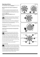
2. Range Overview The dual fuel single cavity range cooker has the following features: A. B. C. D. Fig.2-1 5 hotplate burners including a wok burner A control panel A multi-function oven A storage drawer Cooktop Burners Note: Before using the cooktop make sure all burners are in place and all the grates on the range are properly placed. The drawing by each knob indicates which burner that knob controls (Fig.2-1).
Fig.2-9 Top heat elements Igniting Cooktop Burners without Electricity Broiling elements If there is a power failure the cooktop burners can be lit with a match. A. B. Convection elements ArtNo.326-0001 - Albertine SC - MF oven elements C. Hold a burning match ½” from the burner head, keeping your hand as far horizontally away from the burner as possible. Push and turn the burner control knob to HI/lighting position. As soon as the burner flame lights move your hand away.
Operating the Oven Fig.2-10 The multi-function oven has two controls: a function selector and a temperature setting knob (Fig.2-10). Turn the function selector control to a cooking function. Fig.2-11 shows the control set for conventional oven cooking. Turn the oven temperature knob to the temperature you need. The oven heating light will glow until the oven has reached the temperature you selected. It will then cycle on and off during cooking as the oven maintains the selected temperature (Fig.2-12).
Rack levels 5 and 6 should be used depending on the size of the food being cooked. Fig.2-14 Convection Assisted Oven This function operates the fans, circulating air heated by the elements at the top and the base of the oven. The combination of fan and conventional cooking (top and base heat) makes this function ideal for cooking large items that need thorough cooking, such as a large meat roast.
General Oven Tips Fig.2-15 IMPORTANT: Before using for the first time, to dispel manufacturing odors turn the ovens to 200 °C (395 °F) in Convection Assisted mode and run for one hour. To clear the smell, make sure the room is well ventilated to the outside air, by opening windows for example. Caution! The inside door face is constructed with toughened safety glass. Take care not to scratch the surface when placing cookware on the glass panel. do not close the door against the oven racks.
To remove and refit the racks The rack has a small kink on either side (Fig.2-20). To remove the rack, line these up with the stops in the rack support (Fig.2-21). Lift the rack upwards so that it will pass over the rack stop and then pull it forwards (Fig.2-22). Fig.2-20 Refit in the reverse order, making sure to push it fully back. To remove and refit the telescopic rack and runners Slide the rack out on the runners.
Storage Fig.2-26 The bottom drawer is for storing oven trays and other cooking utensils. It can get very warm, so do not store anything in it, which may melt or catch fire. Never store flammable materials in the drawer. This includes paper, plastic and cloth items, such as cookbooks, plastic ware and towels, as well as flammable liquids. Do not store explosives, such as aerosol cans, on or near the appliance. Flammable materials may explode and result in fire or property damage.
3. Oven Cooking Guide Remember – not all modes will be suitable for all food types. The oven control settings and cooking times given are intended to be used only as a guide only. Individual tastes may require the temperature to be altered to provide a preferred result. Fig.3-1 5 4 3 2 1 ArtNo.050-0019 - Albertine SC - Shelf position Food is cooked at a lower temperature in a convection oven than in a conventional oven.
Cooking Chart ArtNo.030-0015 - Top & Bottom Symbol ArtNo.
4. Cleaning Your Range Part Essential Information Recommended cleaning method Finish Before thorough cleaning, turn off the circuit breaker. Allow the range to cool. Burner grates & Porcelain enamel Mildly abrasive cleaner such as Bon Ami ® or Soft Scrub®. top of burner Dishwasher. heads Burner base Aluminum As above. Maintop top Stainless steel Hot soapy water, non-abrasive cleaner, soft cloth. Sides, toe-kick Painted enamel Hot soapy water and soft cloth.
Never use caustic or abrasive cleaners as these will damage the surface. Fig.4-1 Control Panel and Oven Doors Avoid using any abrasive cleaners including cream cleaners, on brushed stainless steel surfaces. For best results use liquid detergents. ArtNo.311-0030 - Burner head fitting The control panel and control knobs should only be cleaned with a soft cloth wrung out in clean hot soapy water – but take care that no surplus water seeps into the appliance.
5. Troubleshooting Cooktop ignition or cooktop burners faulty If there is an installation problem and I don’t get my original installer to come back to fix it who pays? Is the power on? You do. Service organizations will charge for their service if they are correcting work carried out by your original installer. It is in your interest to track down your original installer.
An oven light is not working Fig.5-1 The bulb has probably burnt out. You can buy a replacement bulb (which is not covered under the warranty) from a good electrical shop. Ask for a 15 W 125–130 V lamp, FOR OVENS. It must be a special bulb, heat resistant to 300 °C (570 °F) (Fig.5-1). ArtNo.324-0005 Oven light bulb Turn off the power at the circuit breaker. Make sure the oven is cool. Open the oven door and remove the oven racks. Fig.5-2 Unscrew the bulb cover by turning counter-clockwise.
WARNING! If the information in this manual is not followed exactly, a fire or explosion may result causing property damage, personal injury or death. Do not store or use gasoline or other flammable vapors and liquids in the vicinity of this or any other appliance. WHAT TO DO IF YOU SMELL GAS Do not try to light any appliance. Do not touch any electrical switch. Do not use any phone in your building. Immediately call your gas supplier from a neighbor’s phone. Follow the gas supplier’s instructions.
INSTALLATION Check the appliance is electrically safe and gas sound when you have finished. 6. Installation Regulations Installation Safety Instructions Installation of this range must conform with local codes, or in the absence of local codes, with the National Fuel Gas Code, ANSI Z223.1/NFPA.54, latest edition. Improper installation, adjustment, alteration, service or maintenance can cause injury or property damage. Refer to this manual.
INSTALLATION Check the appliance is electrically safe and gas sound when you have finished. Location of the Range Checking the parts: Do not locate the range where it may be subject to strong drafts. Any openings in the floor or wall behind the range should be sealed. Make sure the openings around the base of the range that supply fresh air for combustion and ventilation are not obstructed by carpeting or woodwork.
INSTALLATION Check the appliance is electrically safe and gas sound when you have finished. Positioning the Range Fig.6-1 Fig.6-1 and Fig.6-2 show the minimum recommended distances and clearances from the range to nearby surfaces. Min 35½” (90cm) - 36“ (91cm) You must provide adequate clearances between the range and adjacent combustible surfaces. These dimensions must be met for safe use of your range. For Canada, min 363/8” (92.
INSTALLATION Check the appliance is electrically safe and gas sound when you have finished. Fig.6-4 Moving the Range ArtNo.281-0017 - Removing the door The range is very heavy. Take great care. On no account try and move the range while it is plugged into the electricity or gas supply. We recommend two people maneuver the range. Make sure that the floor covering is firmly attached, or removed to prevent it being disturbed when moving the range around.
INSTALLATION Check the appliance is electrically safe and gas sound when you have finished. Installing the Flue Grille The flue grille is packed separately (Fig.6-9). The larger of the holes along the sides are for screwdriver access and should face to the rear. Use the screws and nuts supplied to hold the grille in place (Fig.6-10). ArtNo.280-0029 - Flue Grill Clip the flexible extensions of the oven flues to the flue grille using the clips provided inside the flue grille (Fig.6-11). Fig.
INSTALLATION Check the appliance is electrically safe and gas sound when you have finished. Side Panel Extension kit Fig.6-15 ArtNo.281-0004 - 90SC - Fitting the side panel Two side extension panels are supplied with the range. These can be installed where the side of the range is exposed. The extension installation must be performed by a qualified gas installer, preferably during installation of the appliance (Fig.6-15). ArtNo.
INSTALLATION Check the appliance is electrically safe and gas sound when you have finished. Electrical Connection Gas supply Electrical zone supply zone When installed the range must be electrically grounded in accordance with local codes or; in the absence of local codes with the National Electrical Code ANSI/NFPA 70, latest edition. Range gas inlet Side of range 16” 6” Electrical Requirements 17” 7” In Canada the range must be installed in accordance with the current CSA Standard C22.
INSTALLATION Check the appliance is electrically safe and gas sound when you have finished. 4-Wire Conduit Installation Fig.6-20 Disconnect the supplied power cord from the terminal block and ground post. Keep the terminal block parts; you will need them. Remove the strain relief clamp from the power cord and remove the power cord and strain relief clamp from the mounting bracket (Fig.6-20). The range is shipped with reducer plates to give a 11/8’’ (2.9 cm) diameter opening for conduit connection.
INSTALLATION Check the appliance is electrically safe and gas sound when you have finished. 3-Wire Conduit Installation Fig.6-26 Disconnect the supplied power cord from the terminal block and ground post. Keep the terminal block parts; you will need them. Remove the strain relief clamp from the power cord and remove the power cord and strain relief clamp from the mounting bracket. ArtNo.280-0039 Reducer Plate The range is shipped with reducer plates to give a 11/8’’ (2.
INSTALLATION Check the appliance is electrically safe and gas sound when you have finished. Gas Connection Gas supply Electrical zone supply zone Fig.6-29 Installation of this range must conform with local codes or, in the absence of local codes, with the National Fuel Gas Code, ANSI Z223.1-latest edition.
INSTALLATION Check the appliance is electrically safe and gas sound when you have finished. Connect the Range to the Gas Supply Fig.6-32 Shut off the main gas supply valve before disconnecting the old range and leave it off until the new hookup has been completed. Don’t forget to relight the pilot on other gas appliances when you turn the gas back on.
INSTALLATION Check the appliance is electrically safe and gas sound when you have finished. Seal the Openings Fig.6-33 Seal any openings in the wall behind the range and in the floor under the range when hookups are completed. IMPORTANT: When all connections are completed make sure the flow of combustion and ventilation air to the range is unobstructed. Assemble the Range ArtNo.280-0045 Burner Knob Installing the Control Knobs Fig.6-34 The range is supplied with 5 burner control knobs.
INSTALLATION Check the appliance is electrically safe and gas sound when you have finished. Fitting the Grates Fig.6-40 Make sure that the grates are in the correct position and sitting down (Fig.6-40). Replace the Storage Drawer To replace the drawer in the range, pull the side rails fully out (Fig.6-41). ArtNo280-0084 DF Pan Supports At each side, hold the front of the drawer and pull the side rail forward so that the clips click into position, holding the drawer to the side rails.
INSTALLATION Check the appliance is electrically safe and gas sound when you have finished. Range operational checks How To Move the Range for Servicing Oven Check Follow these procedures to remove appliance for servicing: • • Shut off the gas supply and turn off the circuit breaker. Disconnect gas supply tubing to appliance and unplug the electrical supply cord. Note: A suitably qualified person should disconnect and reconnect the gas supply.
WARNING! If the information in this manual is not followed exactly, a fire or explosion may result causing property damage, personal injury or death. Do not store or use gasoline or other flammable vapors and liquids in the vicinity of this or any other appliance. WHAT TO DO IF YOU SMELL GAS Do not try to light any appliance. Do not touch any electrical switch. Do not use any phone in your building. Immediately call your gas supplier from a neighbor’s phone. Follow the gas supplier’s instructions.
INSTALLATION Check the appliance is electrically safe and gas sound when you have finished. 7. Conversion to LP Gas Important Fig.7-1 • • • Observe all governing codes and ordinances. The range must be properly grounded. Save these instructions for the local electrical inspector’s use. When servicing or replacing gas carrying components disconnect from gas before commencing operation and check appliance is gas sound after completion.
INSTALLATION Check the appliance is electrically safe and gas sound when you have finished. Replace the rings on the burners. Screw in the hexagon headed venturi to make fitting the burners easier. Do not tighten yet. Fig.7-2 Fig.7-3 ArtNo.0102-0001 - Unscrewing the control valve bypass screw When all the burner bases and venturis have been fitted tighten the venturi nuts. Valve adjustment Pull off all the control knobs. ArtNo.
INSTALLATION Check the appliance is electrically safe and gas sound when you have finished. Type 1 Fig.7-7 Unscrew the hexagonal nut in the front of the regulator. The regulator nut has a plastic snap-in converter device on the underside (Fig.7-7). To convert the regulator snap the device out of the nut and replace the other way up. ArtNo.103-0006 - Maxitrol cap & converter The snap-in converter device is marked to show which gas it is set for (Fig.7-8).
INSTALLATION Check the appliance is electrically safe and gas sound when you have finished. Replace the storage drawer Fig.7-12 To replace the drawer in the range, pull the side rails fully out (Fig.7-13). At each side, hold the front of the drawer and pull the side rail forward so that the clips click into position, holding the drawer to the side rails (Fig.7-14). ArtNo.102-0011 - Pressure test point Check the appliance is gas sound. Do not use a flame to check for gas leaks.
8. Service and Parts Please complete the appliance details opposite and keep them safe for future reference – this information will enable us to accurately identify your particular appliance and help us to help you. Filling this in now will save you time and inconvenience if you later have a problem with your appliance. It may also be of benefit to keep your purchase receipt with this leaflet. You may be required to produce the receipt to validate a warranty service visit.
9. Circuit Diagram L1 L2 L1 L2 bk r N N w ArtNo.
10. Technical Data INSTALLER: Please leave these instructions with the user. DATA BADGE LOCATION: Inside base drawer of cavity. Remove the drawer (see Overview > Storage for details). COUNTRY OF DESTINATION: USA/Canada Connections Electric ArtNo280-0090 Drawer Cavity & Badges 240 V 60 Hz Gas ½” NPT at rear left-hand side Dimensions Overall height minimum 3515/16” (910 mm) maximum 367/8” (937 mm) Overall width 35½” (900 mm); see ‘Positioning of Cooker’.
AGA CONSUMER PRODUCTS