
Installation & User Guide

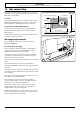
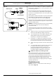
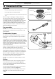
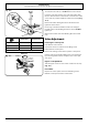

Table Of Contents
- 1. Important safety information
- 2. Range overview
- 3. Cooking tips
- 4. Cooking table
- 5. Cleaning your range
- 6. Troubleshooting
- 7. Installation Instructions
- 8. Service and parts
- 9. Installation safety instructions
- 10. Installation
- 11. Gas connection
- 12. Conversion to LP Gas
- 13. Electrical connection
- 14. Final fitting and checks
- 15. Circuit diagram
- 16. Technical data
- 17. Warranty

32
INSTALLATION
Check the appliance is electrically safe when you have nished.
Save the orices removed from the appliance for future use.
To install the new orices; see Table 12. 1 for orice details.
Insert the new orice into the open end of the rubber tube
which is attached to the socket wrench. Screw into the orice
carrier as far as possible and lift the socket wrench away (Fig.
12.4).
Remove the rubber tubing from the socket wrench and
tighten all of the orices.
Fit the ring on the burner if tted. Screw in the hexagon
headed venturi to make tting the burners easier. DO NOT
tighten yet.
When all the venturis have been tted, tighten the venturi
nuts.
Valve Adjustment
Removing the control panel
Pull o all the control knobs.
Open both oven doors and remove the xing screws
underneath the control panel.
Remove the 3 xing screws at the top of the control panel.
Pull the control panel forward. Taking care not to damage it,
by protecting it with cloth for example, rest it on the open
oven doors.
Bypass screw adjustment
Turn the bypass screw on each control clockwise to the stop
(Fig. 12.5).
Reassemble
Replace the control panel and secure with xing screws.
Ret the control panel and the control knobs.
Table 12.1
Fig. 12.4
Natural Gas Propane Gas*
Center burner
205 118
Large Burners
150 99
Right front burner
112 68
* Jets and labels can be found in the accompanying bag
ArtNo.0102-0011 - Screwing
the control valve bypass screw
Fig. 12.5