
User and Installation Guide

32
INSTALLATION
Check the appliance is electrically safe when you have nished.
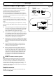
This appliance was converted on
month -day -year
To gas
with kit No
*by
(name and address of organization making this
conversion), which accepts the respomsibility
that rhis conversion has been properly made.
K085791
Q042326
ArtNo.102-0011 - Pressure test point
ArtNo.102-0007 - Maxitrol converter device positions
ArtNo.103-0006 - Maxitrol cap & converter
Nut
Snap-in converter device
ArtNo.102-0005 - Gas regulator types
Fig. 11.6
Fig. 11.7
Fig. 11.8
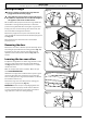
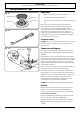
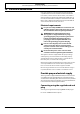
Gas regulator adjustment
NOTE: To avoid exterior damage to the storage drawer. Place
a soft cushioned mat on the oor.
To access the gas regulator remove the storage drawer (see
Removing the drawer). Once the drawer has been removed
the regulator is now visible (Fig. 11.6).
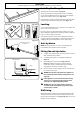
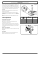
1. Unscrew the hexagonal nut in the front of the regulator.
The regulator nut has a plastic snap-in converter device
on the underside (Fig. 11.7). To convert the regulator
snap the device out of the nut and replace the other
way up.
2. The snap-in converter device is marked to show which
gas it is set for (Fig. 11.8). Make sure the device is
secure in the base of the nut and replace the nut to the
regulator.
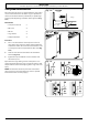
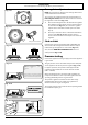
Stick on labels
Complete the conversion label (kit number A060048) and
stick it next to the ratings label inside the drawer cavity to
indicate the gas the appliance is now set for (Fig. 11.9).
Also, stick the “NOW ADJUSTED FOR LP GAS” label in a
similar position (Fig. 11.10).
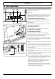
Pressure testing
Connect the appliance to the gas supply. Check the appliance
is gas sound.
The gas pressure can be measured at the pressure test point
on the appliance side of the pressure regulator (Fig. 11.11).
For proper operation, the pressure of LP supplied to the
regulator must be between 10’’ and 13’’ of water column
(2.49 – 3.24 kPa).
When checking for proper operation of the regulator, the
inlet pressure must be at least 1’’ (0.25 kPa) greater than the
operating (manifold) pressure as given above.
The pressure regulator located at the inlet of the range
manifold must remain in the supply line regardless of
whether natural or LP gas is being used.
The pressure with at least 2 surface burners operating should
be 10” WC for Propane gas.
ArtNo.102-0010 - Adjusted to LP gas label
Fig. 11.9
Fig. 11.10
Fig. 11.11