INSTALLATION, MAINTENANCE AND USE INSTRUCTIONS FOR FREE-STANDING COOKERS 90x60 cm GIANT OVEN APPLY DATA LABELS 3100248 1
READ THE INSTRUCTION BOOKLET BEFORE INSTALLING AND USING THE APPLIANCE. It is important that you retain these instructions, proof of purchase as well as other important documents about this product for future reference. The manufacturer will not be responsible for any damage to property or to persons caused by incorrect installation or improper use of the appliance. Due to continual product development, Bertazzoni Group reserves the right to alter specifications and appearances without notice.
WARNINGS: 1. This appliance is not intended for use by persons (including children) with reduced physical, sensory or mental capabilities, or lack of experience or knowledge, unless they have been given supervision or instruction concerning the use of the appliance by a person responsible for their safety. Children should be supervised to ensure that they do not play with the appliance. 2. DO NOT USE OR STORE FLAMMABLE MATERIALS IN THE APPLIANC STORAGE DRAWER OR NEAR THIS APPLIANCE.
LOCAL AUTHORITY REQUIREMENTS Before installation, unpack all parts from carton, remove all internal packaging and check for da mage. Check Gas Type and specifications plate placed on the rear of the unit, alternatively there is a second label supplied. All gas fitting work, service and repairs can only be performed by an authorised person in accordance with AS/NZS 5601 and local gas regulations. Failure to comply with this condition will void the warranty.
IMPORTANT INFORMATION FOR INSTALLING AND SERVICING THE APPLIANCE The cooker can be installed separately, as a freestanding unit, or between kitchen units or between a kitchen unit and the wall. This appliance is not connected to devices which exhaust combustion products. Special attention must be focused on the prescriptions described below regarding room aeration and ventilation.
STEP 4: VISUAL CHECKS The following visual check must be performed to ensure that the conversion has been carried out properly and without damage to other components of the range. Verify that the flame of the oven burner be completely blue and with regular aspect as shown below. CONNECTION OF THERMOCOUPLE TO THERMOSTAT The thermocouple for oven burner is connected to the magnet. Tight gently the connection.
Fig. 05 Fig. 06 APPLIANCE GAS CONNECTION IMPORTANT: This appliance must be installed by an authorised person. WARNING: DO NOT MODIFY THIS APPLIANCE If the appliance cannot be adjusted to perform correctly, contact the service department. This appliance utilises a threaded 1/2" gas male fitting. To connect the appliance to the gas network with a flexible hose, a supplemental hose nipple fitting is needed which is supplied with the appliance. (Fig. 07) Fig.
Using a Copper Pipe connection The cooker must be connected to the gas supply with upstream connection of an isolation valve in accordance with the respectively valid regulations. We recommend that the isolation valve be fitted prior to the cooker to enable isolation of the cooker from the gas supply. The valve must be easily accessible at all times. To find out the gas type factory settings, see label on the rear of the appliance.
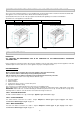
SUPPORT LEGS AND BACKGUARD INSTALLATION The cookers are supplied with four transit supports (one for each corner). Four support legs are supplied separately and are fitted on location to the four corners of the lower support frame. Each support leg is pushed over the relevant transit support until flush with the support frame. Each leg is adjusted by screwing the lowe r section in or out as required for fitting to a 900mm bench height.
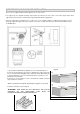
ANTI-TILT DEVICE AND STRAIN RELIEF FLEXIBLE HOSE BEVICE ANTI-TILTING CHAIN/HOSE RESTRAINING CHAIN A chain must be fitted by the installer within 50mm of the hose connection point to prevent strain on the hose when the cooker is pulled forward. The chain should restrict the appliance movement to no more than 80% of the hose length. After the chain is installed, check that there is no strain on the hose or gas connections when the cooker is pulled as far forward as the chain allows.
Left Side In order to prevent the oven from tipping forward as shown on the previous page, we need to make sure both chains provided with the oven are used. On the left side of the oven a 16mm drill bit was used to drill through the cabinetry into the adjacent cabinet, as you can see the hole has not been drilled hard up against the wall because there is a 16 mm board at the rear of the cabinet. The heigt of the hole from the floor is level with where the chain attaches to the oven.
WARNING: In order to prevent accidental tipping of the appliance, for example a child climbing onto the open oven door, the stabilising means must be installed. Ensure the chains are correctly anchored to prevent the appliance from tilting forward and to prevent strain on the hose when the cooker is pulled forward. MAKE SURE THE ANTI-TILTING CHAINS ARE TAUGHT WHEN ANCHORED TO PREVENT THE APPLIANCE TILTING.
4) Unscrew the nozzles using a 7 mm spanner, and replace them (Fig.12) with those needed for the new type of gas according to what is indicated in the Energy Consumption Table. Fig.12 5) Burner "MINIMUM" adjustment: Work surface burner adjustment: follow the instructions below to adjust the work surface burner minimum: Light the burner and set the knob to the MINIMUM position (small flame). Remove the knob of the valve that is press fit on the rod of that valve.
APPLIANCE ELECTRICAL CONNECTION The electric connection must comply with the current legal standards and regulations. Before making the connection, check that: • The system electrical rating and the current outlet are adequate for the maximum power output of the appliance (see the label applied to the bottom of the casing). • The outlet or the system is equipped with an efficient ground connection in accordance with the current legal standards and regulations.
INSTALLATION CHECKLIST 1. Is the range mounted on its legs? 2. Is the backguard securely connected? 3. Has the anti-tip device been properly installed? 4. Does the clearance from the side cabinets comply with the manufacturers directions? 5. Is the electricity properly grounded? 6. Is the gas service line connected following the directions of the manufacturer? 7. Have all the proper valves, stoppers and gasket been installed between the range and the service line? 8.
APPLIANCE USE AND MAINTENANCE ATTENTION: Important Warnings. ATTENTION: TAKE CARE DO NOT OBSTRUCT THE OUTLET OPENINGS ON THE BACKGUARD; THEY MUST BE UNOBSTRUCTED FOR PROPER OPERATION ATTENTION: • For cookers resting on base ATTENTION: if the cooker rest on a base, take the measures necessary to prevent the cooker from sliding along the support base. • For cookers with electric ovens ATTENTION: The unit becomes hot during use. Do not touch the heating elements inside the oven.
WARNING: Before replacing the bulb, disconnect the appliance from the electric power supply. WARNING: The power cord supplied with the appliance is connected to the appliance with an X type connection (in compliance with standards AS/NZS 60335-1, AS/NZS 60335-2-6 and subsequent amendments) for which it can be installed without the use of special tools, with the same type of cord as the one installed. If the power cord becomes worn or damaged, replace it based on the information reported in table 2.
this position until the burner ignites, and then wait 2 seconds for the thermocouple to heat up. Release the control knob and adjust to the correct setting. Fig. 18 -Use of the dual burner (Fig19) This model controls both the central and external crown of the burner with just one valve. To ignite the central crown press and turn the knob to the maximum delivery position 1 and hold it down until ignition: in this position the internal flame are at maximum.
USING THE GAS OVEN GAS OVEN: All the gas oven cookers are equipped with a thermostat and safety device to adjust the cooking temperature. The oven temperature is set by turning the knob counterclockwise to match the indicator with the temperature selected. The gas oven can be combined with a gas grill or an electric grill. See the specific pages for use information.
which can be used to insert shelves or the tray. To keep the oven as clean as possible it is recommended to cook meat on the tray or on the shelf that has been inserted inside the tray.
USING THE OVEN THERMOSTAT CONTROL KNOB The thermostat is used to set the maximum internal temperature of the oven. Turn the thermostat control knob clockwise and align the selected temperature indicated on the knob with the index etched on the control panel above it. Thermostat operation is indicated by an orange light which will turn off when the temperature inside the oven is 10°C greater than the temperature setting, and will turn on when the oven is 10°C less than the temperature setting.
used for longer grilling times, or when grilling foods with a lot of moisture. FAN ASSIST COOKING FUNCTION: This function runs the upper and lower elements, and runs both rear internal fans. It is dependent on the timer and the thermostat setting. Best used when cooking large amounts of food at one time, for frozen potato products and crumbed/battered chicken or fish. FAN OVEN COOKING FUNCTION: This function runs the circular rear elements; and runs both rear internal fans.
minutes before inserting the trays. Adjust oven function control knob to fan oven cooking and place food inside oven. Set timer if needed. grilling The grill is controlled using the oven’s temperature knob. The grill function uses both elements at the top of the oven, so is faster and more powerful than using the top element alone. Run this function with the door closed and at a temperature not exceeding 150°C for up to 15 minutes.
The maximum time is 10 h. The format change will happen after 99 minutes and 50 seconds to 1 hour and 40 minutes. The pot- symbol illuminated. To show time of day press “time of day” button for 6 seconds. Reset timer Count down to zero with permanent pressing “ – “ button. (automatic stop at zero ) Signal The signal after “time out” will stay 7 minutes if it has not been reset with “time of day” button. The following signal will be skipped if time of day is pressed during the last 15 seconds of the timer.
USING THE ANALOG CLOCK (fig.28) For setting up the time displayed by watch pointers push briefly twice the knob till getting the CLOCK icon flashing. For increasing or decreasing time displayed 1 minute by 1, turn the knob clockwise or counterclockwise, le minutes pointer will increase or decrease 1 minute by minute clockwise or counterclockwise.10 seconds after last set up the electronic timer will exit time set up mode.Minute minder set up will activate a simple alarm when set up time is over.
When the start time is reached (end time – duration), the cook pot symbol appears again and the oven becomes active. When the end time has been reached, the oven and the cook pot symbol are turned off. An audible signal sounds and the symbol “A” will begin to flash. Reset the oven to off using the oven control knob and press any of the 3 buttons to the left to stop the audible sound. Minute minder Press the minute minder button and set required time with the +/- buttons.
10h). The selected time is automatically processed by the programmer in a few seconds, or you can also touch the M key many times just to see again the current time. The A and (2) symbols will be on the display. Once the set cooking time is finished, a sound will be heard and the oven automatically switches off. Please see the following paragraphs about how to disable the sound alarm and restarting the oven.
USING THE THERMOMETER (fig.31) The cooker is fitted with a device to measure the temperature in the middle of the oven. This lets you check the temperature inside the oven and adjust food cooking temperatures more accurately. Electric oven When you turn on the oven, the orange light comes on to indicate that the heating elements are working: The thermometer dial will start to move towards the set temperature.
Cleaning the enamelled parts The trivets and burner covers are cast iron with an enamel coating. To maintain the original features of the enamelled parts they should be cleaned frequently with soapy water. Never use abrasive powders. Do note leave acidic or alkaline substances on the enamelled parts (vinegar, lemon juice, salt, tomato sauce, etc.) and do not wash the enamelled parts while they are still hot.
TROUBLESHOOTING If you have a problem with your appliance, check the following before contacting service. PROBLEM SOLUTION Oven or hob not working Check the electricity is turned on. Check your fuses. If the fuse continues to blow, call Bertazzoni Group service. Check the circuit breaker. Ensure correct knob is positioned correctly. Dry or clean ignition electrodes. Make sure flame ports and ignition areas are clean and dry. Check gas main supply is on. Ensure cap/crown correctly fitted.
APPLY WIRING DIAGRAM LABELS BERTAZZONI GROUP ABN 38 069 686 326 650 Bridge Road, Richmond, Victoria 3121 Service & Spare Parts: 1300 748 308 Bertazzoni After Sales Service - P.O. Box 543 SOMERTON VIC 3061 Email: customercare@bertazzonigroup.com.