Installation and Operation Instructions Document 2110A F O T DuraFlowU N O O I T C U D O R P Installation and Operation Instructions for 2400-382A Water Heater A subsidiary of BRADFORD WHITE Corporation
LAARS Heating Systems Company Page 2 TABLE OF CONTENTS SECTION 1. General Information SECTION 2. Remote Bulb Aquastat Controller 1A. 1B. 1C. 2A. 2B. 2B-1. 2B-2. 2C. 2D. Introduction ................................................... 3 Piping ........................................................... 3 Wiring ........................................................... 5 Application .................................................... 5 Installation ...................................................
DuraFlow Water Heater Page 3 SECTION 1. General Information 1A. Introduction The DuraFlow water heater / buffer was designed and developed specificaly as a companion for modern low mass, high efficiency heating boilers. When piped between the supply and return it provides a twenty gallon buffer in the hydronic system. This is typically required in systems with three or more zones to store and release heating capacity when only a single zone is operating.
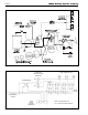
LAARS Heating Systems Company Page 4 F O T U N O O I T C U D O R P Figure 3. Piped as Buffer and Indirect. ZONE THERMOSTATS DURAFLOW WATER HEATER AQUASTAT TRANSFORMER NO RELAY C NC ZONE VALVES L2 L1 DISCONNECT SWITCH LOW MASS BOILER TERMINALS Figure 4. Zoning with Valves. L2 G L1 T T NOTE: Pump Operates From C1-C2 Terminals On Boiler Aquastat.
DuraFlow Water Heater 1C. Wiring Wire relay (see Figure 4) to reverse acting aquastat (supplied) to start boiler and system pump. For maximum domestic water capacity, aquastat must be wired in priority (as shown) or utilize multiple zone relay with priority. Page 5 SECTION 2. Remote Bulb Aquastat Controller 2A. Application This remote bulb, immersion-type controller operates in response to temperature changes in hydronic heating systems and in other heated liquids.
LAARS Heating Systems Company Page 6 2C. Adjustments Set the differential to correspond with the boiler manufacturer recommendations. To adjust models with adjustable differential, rotate the wheel on the back of the snap switch until the desired reading is aligned with the V notch in the frame. The wheel provides an adjustment from 5 to 30 degrees (F). Replace the cover on the aquastat controller. Adjust the control point to correspond with the boiler manufacturer's recommendations.
DuraFlow Water Heater Page 7 F O T U N O O I T C U D O R P
Laars Warranty DuraFlow Water Heater This product is backed by this limited twenty year warranty to assure your complete satisfaction. Laars warrants each DuraFlow to be free from defects in material and workmanship according to the following terms, conditions and time periods: COVERAGE: A. First Year Warranty includes repair replacement, at the option of Laars, of all parts which within one year after original installation are found to be defectively manufactured. B.