
Installation, Operation and Maintenance Instructions User guide


DuraFlow Water Heater
Page 5
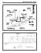
Figure 5. Internal View of Remote Bulb Aquastat
Controller.
1C. Wiring
Wire relay (see Figure 4) to reverse acting
aquastat (supplied) to start boiler and system pump.
For maximum domestic water capacity, aquastat must
be wired in priority (as shown) or utilize multiple zone
relay with priority.
Figure 6. Mounting the Boiler Fitting.
SECTION 2.
Remote Bulb Aquastat Controller
2A. Application
This remote bulb, immersion-type controller
operates in response to temperature changes in
hydronic heating systems and in other heated liquids.
It provides spdt switching for three wire circuit
applications, combining low limit and circulator
control.
Switch ratings are shown on the inside cover.
The electrical requirements of controlled equipment
must not exceed these ratings.
The R to B contacts make to start the boiler when
the boiler water temperature drops to the dial setting
less the differential. The R to W contact breaks to
prevent circulator operation. When the boiler water
temperature rises to the dial setting, R to B breaks and
R to W makes (see Figure 5).
2B. Installation
WARNING
CAN CAUSE PROPERTY DAMAGE, SEVERE
INJURY OR DEATH. This product is intended for
use only in systems with a pressure relief valve.
Caution
Disconnect the power supply before beginning
installation to prevent electrical shock or equipment
damage.
2B-1. Mounting with Boiler Fitting
1. Screw the fitting into the boiler or pipe
tapping.
2. Place the packing nut on the tubing.
3. Slide the bulb completely through the
fitting to bottom third of tank.
4. Place the composition disk and four slotted
brass washers on the tubing in the order
shown in Figure 6. Turn brass washers so
that the slots are 180 degrees to each other.
5. Slide the seal assembly into the fitting and
tighten the packing nut.
2B-2. Wiring
Be sure all wiring agrees with applicable codes,
ordinances, and regulations for wire size, type of
insulation, and enclosure. The controllers are provided
with conduit knock-outs in the top and bottom of case.
Refer to Figure 7 for typical connection diagram.
OUT OF
PRODUCTION