Tankless Gas Water Heater SERVICE MANUAL Troubleshooting Guide and Instruction for Service (To be performed ONLY by qualified service providers) For the LAARS® Heating System EverHot® Exterior Tankless Gas Water Heater Models: IGE-199R-10(N,X) Document 11014 Save this manual for future reference IGE-199C-5(N,X)
Key to Warning Symbols Failure to comply with the following instructions may results in serious personal injury or damage to the appliance. Be careful of possible electric shock. Wiring inside this appliance may potentially be at 120 volts. Disconnect power supply to unit when carrying out the following service repairs. Read Fault Diagnosis and Wiring Diagram carefully to avoid incorrect wiring. Do not disassemble. Parts within can not be exchanged or diagnosed faulty.
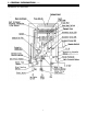
TABLE OF CONTENTS Section Description Page --Glossary of Terms and Symbols..................................................... I ......................General Information........................................................................ a. How to Use This Manual. ................................................ b. Cut Away illustration. ...................................................... c. Schematic illustration. ..................................................... II .....................
GLOSSARY OF TERMS AND SYMBOLS This glossary of terms and symbols is provided to assist you in understanding some of the language used throughout this manual. dB(A) DC AC WFCD FB Hz IC BTU/H PSI LED GPM mA W.C.
I - GENERAL INFORMATION This tankless water heater is a high output, high efficiency appliance, which heats the water continuously as hot water is being drawn for use. Unlike tank type storage water heaters, this water heater does not store hot water. The burner operates whenever there is a demand for hot water and is off when the water flow stops. Hot water is continuously supplied for any length of time required, as long as the specified flow rates are not exceeded.
I - GENERAL INFORMATION (cont.) HOW TO USE THIS MANUAL It is intended for this manual to be used by qualified service personnel for the primary purpose of troubleshooting analysis and repair of this tankless gas fired water heater. Understanding the basic operation of the "Main Components" and the "Sequence of Operation" sections of this manual will contribute greatly to your success in the troubleshooting analysis of this product. Sections of this manual reference general information and specifications.
I - GENERAL INFORMATION (cont.
I - GENERAL INFORMATION (cont.
II - SPECIFICATIONS – GENERAL Type of appliance Operation Exhaust system Model Type Maximum/Minimum gas rate (Input Btu's) Thermal Efficiency Energy Factor (EF) Capacity (Gallons 1st Hour @ 90°F rise) NOx Emissions (at 3% 02) Hot water capacity (50°F rise) Setpoint Temperature (without remote) Temperature range with remote keypads connected Approved gas type Installation Dimensions Weight Noise levels Connections Ignition system Electrical consumption Water temperature control Water flow control Recommen
II - SPECIFICATIONS – GENERAL (cont.) Power Supply Safety Devices Remote control cable Clearances from combustibles Clearances from eaves, porches, overhangs Appliance – 120 Volts A.C. – 60 Hz. Remote control 12 volt D.C.
II - SPECIFICATIONS (cont.) COMBUSTION SPECIFICATIONS Item Gas Consumption Injector Diameter Inches (mm) Main Burner Main Damper Gas Pressure Supply/Manifold Gas Type Natural Propane Minimum Btu's 15,000 15,000 Maximum Btu's 199,000 199,000 Upper ø.045 (1.15mm) ø.029 (.75mm) Lower ø.070 (1.8mm) ø.045 (1.15mm) B3A7-1 (Lean and Rich Bunsen Burner) H73-115 (Upper: ø6, Lower: Not Used) Minimum Supply Maximum Supply Low Fire Manifold High Fire Manifold 11 6" W.C. 10.5" W.C. 0.56" W.C. 3.4" W.C. 10" W.C. 13.
II - SPECIFICATIONS (cont.) DIP SWITCH SETTINGS DANGER Do not attempt to adjust dip switch settings from there factory default settings. Doing so will result in damage to unit, property damage, personal injury or death. Contact Technical Support for information pertaining to dip switch function.
III - MAIN COMPONENTS 1. Mechanical Water Regulator The unique water regulator mechanism ensures the hot water is maintained with no noticeable change to the desired temperature during use, even if water pressure drops due to another tap being turned on and increasing the demand. 2. Preset Bypass A preset volume of cold water is mixed with water heated in the heat exchanger. 3. Burner The burner assembly is made up of 16 identical stainless steel Bunsen burners, secured by an aluminized steel framework.
III - MAIN COMPONENTS (cont.) 5. Combustion Fan Air for the combustion is supplied by a centrifugal fan driven by a DC motor. After a pre-purge period of 0.2 seconds, the fan speed is controlled by the PCB to provide the correct volume of air for combustion. The calculation for the fan speed is based upon incoming water temperature, water flow and the temperature selected on the remote controls. The actual speed of the motor is continuously monitored by a magnetic pulse sensor.
IV - SAFETY DEVICE FUNCTION Flame Failure Situated to the right of the burner in the front of the combustion chamber, the flame rod monitors the combustion process. This sensor monitors the flame intensity, while the PCB compares this signal to the feed back signal from the combustion fan motor, water flow control, and gas flow through the POV valve. If any one of the feedback signals are incorrect, the unit will shut off, preventing discharge of gas to the burner.
IV - SAFETY DEVICE FUNCTION (cont.) Over temperature Cut-Off The temperature of the outgoing hot water is constantly monitored by the water temperature thermistor located near the outlet of the appliance. If the outgoing water temperature reaches 5 °F above the preset temperature, the burner will automatically deactivate. The burner will ignite again when the outgoing hot water temperature falls below the preset temperature.
V - SEQUENCE OF OPERATION The preset temperature is selected at one of the remotes controls (where fitted). Where no remote control is fitted , the default temperature can be set at 108, 120, 130, 140, 150, 160, 170, or 180 °F. To select one of the above temperatures as your default setting, you MUST obtain written permission and training. (Contact your technical service group) When the unit is first plugged into 120 volts, the PCB assumes an incoming water temperature of 77°F.
V - SEQUENCE OF OPERATION (cont.) When the hot water tap is turned off, the water flow sensor stops revolving, and the magnetic pulse ceases, indicating to the PCB that there is no water flowing, in turn the PCB closes the gas valves. The combustion fan continues to operate for 65 seconds. This will provide quicker ignition when the tap is turned on and off in rapid succession, and removes the need for a pre-purge cycle allowing the burner to re-light immediately when a hot water tap is opened again.
V - SEQUENCE OF OPERATION (cont.
V - SEQUENCE OF OPERATION (cont.
V - SEQUENCE OF OPERATION (cont.
V - SEQUENCE OF OPERATION (cont.
VI - TROUBLESHOOTING ERROR MESSAGES Error 10 Faulty Air Supply or Exhaust Blockage 11 No Ignition 12 Flame Failure 14 Thermo Fuse 16 Over Temperature Warning Remedy Check intake and exhaust ports for obstructions. Check that nothing is blocking the flue inlet or exhaust. Did you maintain the proper clearance from combustibles around the unit? Ensure you have gas to the appliance. Ensure gas type and pressure is correct. Bleed all air from gas lines. Verify dip switches are set properly.
VI - TROUBLESHOOTING (cont.) ERROR MESSAGES Error 32 Faulty Outgoing Water Temperature Sensor Faulty 33 Heat Exchanger Outgoing Temperature Sensor Faulty 34 Combustion Air Temperature Sensor Faulty 52 Modulating Solenoid Valve Signal Abnormal 61 Combustion Fan Failure 71 SV0, SV1, SV2, and SV3 Solenoid Valve Circuit Faulty 72 Flame Sensing Device Faulty LC Scale Build-up in Heat Exchanger No Code Nothing happens when water flow is activated Remedy Check sensor wiring for damage.
VI - TROUBLESHOOTING (cont.) QUICK REFERENCE DIAGNOSTIC POINTS IMPORTANT SAFETY NOTES: There are a number of (live) tests that are required when fault finding this product. Extreme care should be used at all times to avoid contact with energized components inside the water heater. Only trained and qualified service agencies should attempt to repair this product.
VI - TROUBLESHOOTING (cont.) Thermal Fuse: Red ~ Red 100 VAC Below 1 ohm B~C B6 ~ C1 Overheat Switch: Red ~ Red 100 VAC Below 1 ohm B~C B6 ~ C1 Flame Rod: Place one lead of your meter to the flame rod and the other to earth or ground. With the unit running you should read between 5 ~ 150 VAC. Set your meter to the µ amp scale, series your meter in line with the flame rod. You should read 1µ or greater for proper flame circuit.
VI - TROUBLE SHOOTING (cont.) Using a voltage meter set to the 200 ohm scale, you should have a resistance reading of 26 - 30 ohms through each of these heaters. The heater located on the heat exchanger piping should have a resistance reading of 81 – 86 ohms and the one located in the water flow sensor valve has a resistance reading of 16 – 19 ohms. Voltage throughout this circuit should be 120 VAC. Fuses: This unit has 2 in line (3) amp glass fuses. Remove the fuse and check continuity through them.
VI - TROUBLE SHOOTING (cont.
VI - TROUBLESHOOTING (cont.) Troubleshooting Flow Chart BEFORE CARRYING OUT CHECKS MARKED WITH A # SIGN, DISCONNECT THE POWER SUPPLY. Nature of Fault A. The LED on the remote control does not light up, when the system is powered up Examination Point 1. Do you have voltage to the unit? 2. Is supply voltage correct? 3. Check surge protector. 4. Check both 3 amp electrical fuses. 5. Check for short circuits.
VI - TROUBLESHOOTING (cont.) Troubleshooting Flow Chart BEFORE CARRYING OUT CHECKS MARKED WITH A # SIGN, DISCONNECT THE POWER SUPPLY. Nature of Fault Examination Point Values Diagnostic Point 2. Measure the voltage at connector F with appliance power supply on. 7. Check remotes (s) (where connected.) Y/N Action Are values within those specified at left. Yes Go to A – (7) No Replace transformer 11 ~ 13 VDC Digital Yes 1. Measure voltage between red ~ black of connector B4. (See page 35) 2.
VI - TROUBLESHOOTING (cont.) Troubleshooting Flow Chart BEFORE CARRYING OUT CHECKS MARKED WITH A # SIGN, DISCONNECT THE POWER SUPPLY. Nature of Fault Error code "11" displayed on digital monitor. Examination Point 5. Check ignition module. Values 1. Measure voltage between grey ~ grey of connector F8 (ignition module).(See page 37) 2. # Remove connector F8 and measure the resistance between ignition module and terminals. (See page 37) 3. Check if unit is sparking. 6.
VI - TROUBLESHOOTING (cont.) Troubleshooting Flow Chart BEFORE CARRYING OUT CHECKS MARKED WITH A # SIGN, DISCONNECT THE POWER SUPPLY. Nature of Fault C. Combustion occurs, but flame fails. Error code "12" displayed on digital monitor. Examination Point 1. Check flame rod. 2. Check ground wire. Diagnostic Point Values 1. Measure the voltage between flame rod terminal C1 and appliance ground. 2. Check to ensure flame rod bracket is not loose.
VI - TROUBLESHOOTING (cont.) Troubleshooting Flow Chart BEFORE CARRYING OUT CHECKS MARKED WITH A # SIGN, DISCONNECT THE POWER SUPPLY. Nature of Fault Examination Point Diagnostic Point Values 2. Measure voltage between orange (+) and grey (-) of the water flow servo connector B2. 3. Measure voltage between brown ~ grey of water flow servo connector B2 (Don not turn water on) (See page 42) 4.
VI - TROUBLESHOOTING (cont.) Troubleshooting Procedure BEFORE CARRYING OUT CHECKS MARKED WITH A # SIGN, DISCONNECT THE POWER SUPPLY. Unit’s wiring diagram can be found on page 27. Appliance fails to operate (even remote control fails to operate). 1) Is the fuse blown? Check fuse. a. Disconnect unit from power supply. b.
VI - TROUBLESHOOTING (cont.) 3) Is the remote control normal? Check voltage between the two remote control cable connectors. a. Check the voltage between terminals on the remote control terminal mount D1. Normal: 11 ~ 13 VDC If normal, check for an open circuit or short before replacing the remote control. Faulty: Replace PCB. (Service Procedure IGE-2, page 47) No combustion (despite remote control indication) 1) Is the water flow sensor normal? Check the water flow sensor. a.
VI - TROUBLESHOOTING (cont.) BEFORE CARRYING OUT CHECKS MARKED WITH A # SIGN, DISCONNECT THE POWER SUPPLY. 2) Is the flame rod normal? Error “72” is displayed Checking the flame rod. a. # Detach the flame rod terminal C1, and re-attempt operation. (“72 is displayed) Proceed to check item 3 below. (no “72” displayed) Inspect flame rod wiring for current leak and inspect flame rod for carbon build-up. Measure resistance between the flame rod Terminal C1 and the appliance earth. Normal: 1 M Ω or more.
VI - TROUBLESHOOTING (cont.) BEFORE CARRYING OUT CHECKS MARKED WITH A # SIGN, DISCONNECT THE POWER SUPPLY. 4) Is the combustion fan motor normal? Motor check. If error “61” is displayed, check the combustion fan. a. Measure voltage at connector A1. Black and red wires. Normal: 6 ~ 45 VDC (Fan on) 0 VDC (Fan off) If normal, check item b below. Faulty: Replace the PCB unit. (Service Procedure IGE-2, page 47) Fan revolution sensor check. b. Measure voltage at connector A1, black and yellow wires.
VI - TROUBLESHOOTING (cont.) BEFORE CARRYING OUT CHECKS MARKED WITH A # SIGN, DISCONNECT THE POWER SUPPLY. 6) Is the main gas solenoid valve (SV0) operating normally? If error “11” or “71” is displayed, check the main gas solenoid valve. a. # Disconnect the main gas solenoid valve (SV0) connector and measure the resistance at the solenoid terminals. Normal: 1.7 ~ 2.1 K Ω If normal, check b below. Faulty: Replace gas valve. (Service Procedure IGE-9, page 50) b.
VI - TROUBLESHOOTING (cont.) BEFORE CARRYING OUT CHECKS MARKED WITH A # SIGN, DISCONNECT THE POWER SUPPLY. 9) Is the change over solenoid (SV3) operating normally? If error “11” or “71” is displayed, check the change over solenoid (SV3). a. # Disconnect the changeover solenoid (SV3) connector, and measure the resistance at the solenoid terminals. Normal: 1.7 – 2.1 K Ω If normal, check b below. Faulty: Replace the manifold assembly. (Service Procedure IGE-8, page 49) b.
VI - TROUBLESHOOTING (cont.) BEFORE CARRYING OUT CHECKS MARKED WITH A # SIGN, DISCONNECT THE POWER SUPPLY. Error code “14” Check the thermal fuse. a. # Disconnect connector B3 and C3, measure the resistance between the red – red wires. Normal: Less than 1 Ω If normal, check b below. Faulty: Check manifold gas pressure. Check heat exchanger for cracks and/or separations. If there is nothing abnormal, replace the thermal fuse. (Service Procedure IGE-11, page 51) b.
VI - TROUBLESHOOTING (cont.) BEFORE CARRYING OUT CHECKS MARKED WITH A # SIGN, DISCONNECT THE POWER SUPPLY. Unable to adjust hot water temperature 1) Is the water temperature thermistor operating normally? a. # Disconnect the connector B5, and measure the resistance between the white wires, see below for resistance readings. Thermistor resistance valves: 59 ºF = 11.4 ~ 14 K Ω 86 ºF = 6.4 ~ 7.8 K Ω 113 ºF = 3.6 ~ 4.5 K Ω 140 ºF = 2.2 ~ 2.7 K Ω 221 ºF = 0.6 ~ 0.8 K Ω Normal: Proceed to check item 2 below.
BEFORE CARRYING OUT CHECKS MARKED WITH A # SIGN, DISCONNECT THE POWER SUPPLY. 3) Is the modulating valve operating normally? Error code 52 a. b. # Disconnect the modulating valve festoon C2 terminals and measure the resistance at the terminals. Normal: 67 ~ 81 Ω If normal, check b. Faulty: Replace gas valve. (Service Procedure IGE-9, page 50) Re-connect terminal C2 and measure voltage across the pink ~ pink wires when the unit is firing. Normal: 2 ~ 15 VDC c. If normal, check c below.
BEFORE CARRYING OUT CHECKS MARKED WITH A # SIGN, DISCONNECT THE POWER SUPPLY. Anti-frost heaters do not operate 1) Are the ceramic anti-frost heaters operating normally? a. # Disconnect connector F4, and measure the resistance of the heater mounted in the water flow control valve, these are white wires. Disconnect connector F5, and measure the resistance of the heater in the outlet line connector. See connectors in the first and second picture to the left. Normal: 348 ~ 375 Ω If normal, proceed to b.
VII - GAS PRESSURE SETTING PROCEDURE All settings/adjustments must be performed by a qualified Service Technician. 1. Turn unit off at power source and turn off the gas to the water heater. 2. Remove the front cover from the water heater. 3. Remove the gas pressure test port plug. Connect manometer to this port. (See Figure #1 for location of the test port plug.) Turn on the gas and power to the water heater. 4.
WARNING Dip switched #7 and #8 (combustion control switches) MUST be returned to the "OFF" position, after setting pressures. 8. Turn off the gas to the water heater. Remove the manometer connection. Reinstall the pressure port plug. Turn on the gas to the water heater and check for gas leaks around test port with a leak solution. 9. Reinstall the front cover and place the unit back into operation. 10. Verify the proper water temperature, as set on the controller at your outlets.
VIII - SERVICE PROCEDURE NOTE: Before proceeding with dismantling, be sure to follow the CAUTION instructions before each explanation. Always disconnect the electrical supply, turn off water and gas supply service valves, and drain all water from the unit before proceeding. Only trained and qualified service agencies should attempt to repair this product. Service Procedure IGE - 1. Removal of the Front Panel..........................................................47 IGE - 2. Removal of the PC Board....
WARNING Dip switched #7 and #8 (combustion control switches) MUST be returned to the "OFF" position, after setting pressures. Dip switch #1 MUST be returned to the proper position based upon the length of vent pipe (see page 13). IMPORTANT When dismantling the unit you should always isolate the following items: IGE - 2. Removal of PC board CAUTION 120 volt potential exposure. Isolate the appliance and reconfirm power has been disconnected using a multimeter.
a. b. Remove the four (4) Phillips screws that secure the water inlet filter housing to the unit. See picture below for location of screws. Once screws are removed reach into the unit and pull up and out on the flow control assembly to remove it from the appliance. Inspect o-ring for damage. IGE - 5. Removal of the Combustion Fan: CAUTION 120 volt potential exposure. Isolate the appliance and reconfirm power has been disconnected using a multimeter. a. Disconnect wiring harness from fan motor. b.
IGE - 7. Removal of Transformer: CAUTION 120 volt potential exposure. Isolate the appliance and reconfirm power has been disconnected using a multimeter. a. Remove the combustion fan motor assembly as described in section 5-a,b. b. Remove the two (2) Phillips screws to release the transformer. c. Disconnect wiring harness connectors to transformer and pull out towards you. d. To remove the burner assembly remove (8) Phillip screws around the sight glass panel. Remove this panel. e.
IGE - 9. Removal of the Gas Valve Assembly: b. CAUTION 120 volt potential exposure. Isolate the appliance c. and reconfirm power has been disconnected using a multimeter. a. Remove the burner manifold, refer to section 8-a,b,c. b. Remove the four (4) Phillips screws that hold the gas connection and gas control valve in place at the bottom of the unit. Pull the gas connection down to disconnect it from the gas valve assembly. Inspect o-ring for damage and/or defects.
IGE - 11. Removal of Thermal Fuse: a. CAUTION 120 volt potential exposure. Isolate the appliance b. and reconfirm power has been disconnected using a multimeter. This process may involve removing the heat exchanger if the thermo-fuse on the rear of the heat exchanger is blown. (Service Procedure IGE-10, page 50) 51 The unit has four thermal fuses, see picture below for location. Disconnect and remove the thermal fuse. Re-install new thermo fuse using the existing thermo fuse clips.
IX - FLUSHING PROCEDURE FOR LIME SCALE REMOVAL FROM HEAT EXCHANGER The amount of calcium carbonate (lime) released from water is in direct proportion to water temperature and usage. The higher the water temperature or water usage and the harder the water (more dissolved calcium carbonate), the more lime deposits are dropped out of the water. This is the lime scale that forms in pipes, water heaters and on cooking utensils.
X - PARTS BREAKDOWN DISASSEMBLED VIEW - CABINET 53
X - PARTS BREAKDOWN DISASSEMBLED VIEW - INTERNALS 54
X - PARTS BREAKDOWN DISASSEMBLED VIEW - INTERNALS 55
X - PARTS BREAKDOWN DISASSEMBLED VIEW - ELECTRICAL 56
PARTS LIST Number 001 002 003 004 005 006 007 008 009 011 102 103 104 105 106 107 108 109 110 110 111 112 113 115 116 117 118 119 120 122 123 127 128 132 136 137 138 140 400 401 402 403 404 405 406 407 408 409 410 411 702 703 704 705 706 707 708 709 710 711 Description Front Panel Assembly Casing Assembly Wall Installation Bracket Connection Reinforcement Panel Heat Protection Plate Rubber Bushing Front Panel Gasket Front Panel Gasket - Side Front Air Inlet Grill Rubber Bushing Gas Connection (3/4" NPT) Bu
715 716 717 718 720 721 722 723 725 726 730 731 732 733 734 800 801 802 803 804 805 806 807 808 809 810 813 814 815 817 818 238-44959-00 239-44509-00 239-44510-00 239-44507-00 239-44508-00 120v Valve Heater Assembly Anti-Frost Heater Clip Anti-Frost Heater Clip A Anti-Frost Heater Clip Power Supply Harness Fuse Harness 100v Harness Solenoid Valve Harness Thermal Fuse Harness Mold-type Limit Switch PCB Assembly Surge Protector Frost Sensing Switch 120V Anti-Frost Heater Assembly Sensor Harness - 2 Screw Scr
Notes 59
800.900.9276 • Fax 800.559.1583 (Customer Service, Service Advisors) 20 Industrial Way, Rochester, NH 03867 • 603.335.6300 • Fax 603.335.3355 1869 Sismet Road, Mississauga, Ontario, Canada L4W 1W8 • 905.238.0100 • Fax 905.366.0130 www.Laars.com Litho in U.S.A.