LAARS EverHot® Doc. 11044 EVERHOT® TANKLESS GAS WATER HEATER FOR EXTERIOR INSTALLATION IGE-199R AND IGE-199C MODEL SERIES WARNING: If the information in these instructions is not followed exactly, a fire or explosion may result causing property damage, personal injury or death - Do not store or use gasoline or other flammable vapors and liquids in the vicinity of this or any other appliance - WHAT TO DO IF YOU SMELL GAS • Do not try to light any appliance.
SECTION I: IMPORTANT INFORMATION READ CAREFULLY This gas-fired water heater is design certified by CSA International under the American National Standard, Z21.10.3 (as indicated on the rating plate) and CAN/CGA 4.3-M (as indicated on the rating plate) available from CSA Standards Association, 178 Rexdale Blvd., Etobicoke, Ontario, Canada M9W 1R3. This water heater must be installed in accordance with local codes.
DANGER DO NOT store or use gasoline or other flammable, combustible, or corrosive vapors and/or liquids in the vicinity of this or any other appliance. This water heater is for OUTDOOR INSTALLATION ONLY. DO NOT INSTALL INDOORS. This water heater is equipped with an adjustable thermostat to control water temperature. Hot water temperatures required for automatic dishwasher and laundry use can cause scald burns resulting in serious personal injury and/or death.
WARNING DO NOT tamper with or alter the water heater and/or controls. DO NOT operate water heater with jumpered or absent controls or safety devices. DO NOT operate water heater if any external part has been under water. Immediately call a qualified service agency to inspect the appliance and to replace any part of the control system including gas controls, which has been under water. DO NOT attempt to use this water heater with any gas other than the type listed on the rating plate.
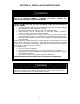
SECTION II: SPECIFICATIONS Max. Flow Rate @ Degree Temperature Rise Model No. IGE-199R-10N IGE-199R-10X IGE-199C-5N IGE-199C-5X Max. Input Rating Btu/hr. 199,000 Min. Input Rating Btu/hr. 15,000 Temp Rise 40°F 60°F 80°F 100°F 120°F 140°F Flow Rate Gal/Min. 7.3 5.9 4.2 3.3 2.8 2.4 First Hour Supply Gal/Hr. 438 354 252 198 168 144 Max. Flow Rate @ Degree Temperature Rise Model No. IGE-199R-10N IGE-199R-10X IGE-199C-5N IGE-199C-5X Max. Input Rating kW/hr. 58.3 Min.
EVERHOT® IGE Model Series Dimensions Dimensions (Inches) Clearances from Combustible Materials: Maximum/Minimum Gas Input Rating, Btu/hr.
SECTION III: GENERAL INFORMATION FEATURES The LAARS EVERHOT® IGE series tankless water heater is a high output, high efficiency appliance, which heats the water continuously as hot water is being drawn for use. Unlike tank type storage water heaters, this water heater does not store hot water. The burner operates whenever there is a demand for hot water and is off when the water flow stops.
SECTION IV: INSTALLATION INSTRUCTIONS WARNING INSTALLATION OF THIS WATER HEATER REQUIRES ABILITY EQUIVALENT TO THAT OF A LICENSED PLUMBER. PLUMBING, AIR SUPPLY, VENTING, GAS SUPPLY AND ELECTRICAL WORK ARE REQUIRED. DO NOT ATTEMPT TO LIGHT ANY GAS APPLIANCE IF YOU ARE NOT CERTAIN OF THE FOLLOWING: • Liquefied petroleum gases/propane gas and natural gas have an odorant added by the gas supplier that aids in detection of the gas. • Most people recognize this odor as a “sulfur” or “rotten egg” smell.
WARNING • • • This water heater is suitable for potable water heating only. DO NOT use this water heater for space heating or combination space heating/domestic water WARNING heating. This water heater is not suitable for use in pool or spa applications. The water heater must be installed outdoors. Failure to properly install this water heater outdoors may result in property damage, personal injury, or death.
Build Opening Clearances (Fig 1) Table 1 Minimum Installation Clearances Reference Description A B C D E F Vertically below a window, door which opens, air inlet Vertically above a window, door which opens, air inlet Below eaves, porches, or overhangs Horizontally from a window, door which opens, air inlet Horizontal distance from another water heater Vertical distance from another water heater Minimum Distance in Inches (cm) 12” (30.5 cm) 12” (30.5 cm) 36” (91.4 cm) 12” (30.5 cm) 2” (5.1 cm) 12 (30.
SECTION V: WATER CONNECTIONS WARNING Failure to install and maintain a new, listed pressure relief valve will release the manufacturer from any claim, which might result from excessive temperature and pressures. Keep clear of the pressure relief valve discharge line outlet. The discharge may be hot enough to cause scald injury. The water is under pressure and may splash. WARNING DO NOT reverse the inlet and outlet (cold and hot water) connections on the water heater.
2. In order to service the water heater in the event the heat exchanger needs to be flushed from lime deposits, tee fittings with shut off valves and service connections to hoses should be installed. Also install a shut off valve to the hot water supply to isolate the service tee fittings. A plumbing installation kit, which includes these fittings and a pressure relief valve, is available from your supplier. Refer to piping diagrams (fig. 2-5) at the end of Section V. 3.
Recommended Piping for a Basic Installation Fig.
Recommended Piping for Power Failure Freeze Protection As long as electrical power and gas are supplied to the EVERHOT® water heater, freeze protection is provided to the heat exchanger and piping inside the water heater with ambient temperatures as cold as -30°F (-34°C), when protected from direct wind exposure. In the event of a power failure at temperatures below freezing, the water heater must be drained of all water to prevent freeze damage.
Recommended Piping for a Circulation System Fig.
Recommended Piping for Back-up Storage System For hotels, motels, and other high flow applications (Fig. 5) Note: The Primary Circulator for the water heating loop must be sized for 21 GPM @ 35 Ft. Head.
PRESSURE RELIEF VALVE WARNING Keep clear of the pressure relief valve discharge line outlet. The discharge may be hot enough to cause scald injury. The water is under pressure and may splash.
SECTION VI: GAS CONNECTIONS WARNING Connect this water heater only to the type of gas as shown on the rating plate. Use clean black iron pipe or equivalent material approved by local codes and ordinances. (Dirt and scale from the pipe can enter the gas valve and cause it to malfunction). The inlet gas line must have at least a 3 inch (7.62 cm) drip leg (sediment trap) installed as close to the water heater’s gas valve as possible.
Check the type of gas and the gas inlet pressure before connecting the EVERHOT water heater to the gas supply. If the gas supply type does not match the type shown on the water heater rating plate, then DO NOT connect the water heater. Contact your supplier for the correct water heater. GAS METER SIZE –NATURAL GAS ONLY Be sure that the gas meter has sufficient capacity to supply the full rated gas input of the water heater as well as the requirements of all other gas fired equipment supplied by the meter.
4. Turn power on (after completing electrical connections – refer to Section VII, “Electrical Connections”) and fully open a hot water tap. 5. Measure the gas pressures to see that these are within the specified limits below: Supply Pressure: Nat. Gas: Min.: 6”, Max.: 10.5” w.c. L.P. Gas: Min.: 10”, Max.: 13.5” w.c. Manifold Pressure: Nat. Gas: 3.4” w.c. High Fire, 0.6” w.c. Low Fire L.P. Gas: 5.1” w.c. High Fire, 0.9” w.c. Low Fire 6. Turn off the hot water faucets.
SECTION VII: ELECTRICAL CONNECTIONS WARNING Turn off or disconnect the electrical power supply to the water heater before servicing. Label all wires prior to disconnection when servicing controls. Wiring errors can cause improper and dangerous operation. Verify proper operation after servicing. All electrical wiring must be installed and grounded in accordance with local codes, or in the absence of local codes, the National Electrical Code, ANSI/NFPA 70 and/or CSA C22.2 Electrical Code.
Wiring Diagram WARNING DO NOT adjust any dipswitch settings on PC board! 22
Wiring Diagram – Schematic 23
REMOTE TEMPERATURE CONTROLS The supplied Remote Main Control allows the customer to control the hot water supply temperature and will display certain fault codes in the event the water heater needs servicing. If used without the Remote Main Control connected, the residential models (IGE-199R-10N,10X) have a fixed temperature setting of 120°F and the commercial models (IGE-199C-5N, 5X) have a fixed temperature setting of 140°F.
°F Priority Set Temperature In Use Main Controller 239-44509-00 endless hot water system CAUTION: Hotter water increases the risk of scald injury. Before changing temperature setting, see instruction manual. Main or Optional Remote Control for Residential Models (Fig. 6) Temperature Control(s) Installation: 1. Determine how many controls will be installed and suitable location(s) for each. The controls may be wired in series or parallel depending on the distance from the water heater to the controls.
WARNING Do not attempt to connect the remote controls with the power on to the water heater. There are 120 volt terminals and wiring next to the remote control connections inside the unit. All servicing and wiring must be performed by a certified installer. 9. Thread the cable through the access hole at the base of the water heater and connect the wires to the control terminals on the right hand side of the PCB. See control wiring illustration (fig. 8). 10.
°F Priority Set Temperature In Use Main Controller 239-44509-00 endless hot water system CAUTION: Hotter water increases the risk of scald injury. Before changing temperature setting, see instruction manual. Control for Commercial Models (Fig. 7) Remote Temperature Control Installation: Follow the same control installation procedure as outlined under “Temperature Control Installation” for residential models. WARNING Do not attempt to connect the remote controls with the power on to the water heater.
SECTION VIII: OPERATING INSTRUCTIONS WARNING Water heaters are heat-producing appliances. To avoid damage or injury there must be no materials stored against the water heater or near the front vent outlet, and proper care must be taken to avoid unnecessary contact (especially by children) with the water heater and front vent outlet.
LIGHTING INSTRUCTIONS FOR YOUR SAFETY READ BEFORE OPERATING WARNING: If you do not follow these instructions exactly, a fire or explosion may result causing property damage, personal injury or loss of life. A. This appliance does not have a pilot. C. Use only your hand to operate the remote It is equipped with a direct ignition control keypad. Never use tools. If the device, which automatically lights remote keypad doesn’t work, do not try to the burner.
CAUTION In climates where below freezing temperatures may occur, the water heater must be drained when power is off to the water heater to prevent freeze damage to the heat exchanger. Drain solenoids are recommended to prevent freeze damage during power failures in cold climate regions. TURNING OFF THE WATER HEATER FOR AN EXTENDED PERIOD OF TIME If the EVERHOT® water heater is to be turned off for an extended period of time, the following steps should be taken. 1.
2. To set the desired temperature on the remote control, all hot water faucets must be closed. If there are other Remote Controls installed, press the “Priority” button on the control you want to change the setting on and the yellow “Priority” indicator light will glow. 3. Press the “H” or “C” button until the required temperature is displayed on the digital monitor. All residential controls have a maximum temperature setpoint of 160°F. 4. To operate the water heater, simply turn any hot water tap on.
Commercial Models (see Figure 11): 1. Commercial models are supplied in the water heater carton with a Remote Main Control, which will allow the outlet water temperature to be adjusted from 98-185°F. When additional Remote Controls are installed, the temperature can only be adjusted on the remote control that has the Priority Indicator Light glowing. The temperature displayed on the control in use will also be displayed on all the other remote controls. 2.
CAUTION Check local codes for the maximum water temperature setting allowed when used in nursing homes, schools, day care centers, and all other public use applications. NOTICE The default temperature setting displayed for commercial controls that will appear when the water heater is first connected to the electrical supply or in the event of a power interruption is 140°F. SCALDING CAUTION Test the temperature of the water with your hand or elbow before placing a child in the bath or shower.
APPROXIMATE TIME/TEMPERATURE RELATIONSHIPS IN SCALDS 120°F (49°C) More than 5 minutes 125°F (52°C) 11⁄2 to 2 minutes 130°F (54°C) About 30 seconds 135°F (57°C) About 10 seconds 140°F (60°C) Less than 5 seconds 145°F (63°C) Less than 3 seconds 150°F (66°C) About 11⁄2 seconds 155°F (68°C) About 1 second FIRST AID FOR SCALDS 1. Remove all wet clothing quickly. Wet clothing retains the heat. 2. Apply cold water to burned area for 30 minutes to reduce the heat in the skin and prevent deeper burning.
SECTION IX: MAINTENANCE WARNING Always turn off the electrical power supply, the manual gas valve, and the manual water control valve whenever servicing this appliance. KEEP THE APPLIANCE AREA CLEAR AND FREE FROM COMBUSTIBLE MATERIALS, GASOLINE, AND OTHER FLAMMABLE VAPORS AND LIQUIDS! Do not block the air inlet openings on the front panel or flue exhaust vent. These openings must be kept free of debris or obstructions for combustion air supply to the burners.
WARNING Before manually operating the valve, make sure that a drain line has been attached to the valve to direct the discharge to an open drain. Failure to take this precaution could mean contact with extremely hot water passing out the valve during this checking operation. FLUSHING PROCEDURE FOR LIME SCALE REMOVAL FROM HEAT EXCHANGER The amount of calcium carbonate (lime) released from water is in direct proportion to water temperature and usage.
Lime Scale Flushing Diagram (Fig 13) COMMON TROUBLESHOOTING COMMENTS ON THE OPERATION OF THE EVERHOT® TANKLESS WATER HEATER Comment: I don’t have any hot water when I open the tap! Make sure the gas and electricity is turned on to the water heater. The remote temperature display should have the green light lit when a hot water tap is open and the water heater is operating. Make sure there are no error codes flashing on the display.
SCHEMATIC DIAGRAM OF INTERNAL PARTS 38
SECTION X: PARTS LIST Cabinet Note: Can purchase additional controls for remote locations.
Internal Components 40
Internal Components 41
Electrical Components 42
Number 001 002 003 004 005 006 007 008 009 011 102 103 104 105 106 107 108 109 110 110 111 112 113 115 116 117 118 119 120 122 123 127 128 132 136 137 138 140 400 401 402 403 404 405 406 407 408 409 410 411 702 703 704 705 706 707 708 709 710 711 715 PARTS LIST Description Front Panel Assembly Casing Assembly Wall Installation Bracket Connection Reinforcement Panel Heat Protection Plate Rubber Bushing Front Panel Gasket Front Panel Gasket - Side Front Air Inlet Grill Rubber Bushing Gas Connection (3⁄4” NPT
Number 716 717 718 720 721 722 723 725 726 730 731 732 733 734 735 801 802 803 804 805 806 807 808 809 810 813 814 815 817 818 238-44959-00 239-44509-00 PARTS LIST Description Anti-Frost Heater Clip Anti-Frost Heater Clip A Anti-Frost Heater Clip Power Supply Harness Fuse Harness 100v Harness Solenoid Valve Harness Thermal Fuse Harness Mold-type Limit Switch PCB Assembly Surge Protector Frost Sensing Switch 120V Anti-Frost Heater Assembly Sensor Harness - 2 Water Flow Sensor Screw Washer Screw Screw Screw