
Service Manual


34
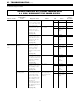
Nature of Fault
Examination
Point Diagnostic Point Values Y/N Action
Service
Procedure
C. Combustion
o
ccurs, but flame
fails.
Error code "12"
displayed on
digital monitor.
1. Check flame rod.
2. Check ground
wire.
1. Measure the voltage
b
etween flame rod
terminal C
1
and
appliance ground.
2
. Check to ensure flame
rod bracket is not loose.
Check for faulty ground
wire connections at unit,
receptacle, and ground
rod to home, and for
broken or shorted wires.
5
~
150 VAC
Is it secure?
Are connections
OK?
Yes
N
o
Yes
No
Yes
No
Go to C-1-2
R
eplace PCB
Go to C-2
Replace/
rectify
Check for
other causes
of flame
f
ailure.
Replace or
repair
grounding
circuit to unit.
IGI – 2
D. Cannot adjust
water
temperature.
1. Chec
k hot water
thermistor.
(outgoing
thermistor)
# Disconnect connect
or
B
5
and measure the
resistance between
white
~
white.
(See page 43)
Resis
tance values
match table on page
43
Yes
No
Go to D – 2
Replace water
temperature
ther
mistor.
IGI – 6
2. Check
changeover solenoid
valve (SV3).
1. # Disconnect
connect
or E from PCB
and measure the
resistance between
brown
~
black.
2. Measure t
he v
oltage
between br
own
~
black
wire of the changeover
solenoid valve (SV3) at
connect
or E.
(See page 41)
1.7
~
2.1KΩ
80
~
100 VDC
Yes
No
Yes
No
Go to D – 2-2
Replace
manifold
assembly
Go to D – 3
Replace PCB
IGI – 8
IGI – 2
3. Chec
k
modulating valve.
1. # Disconnect
modulating valve at C
2
f
es
t
oon terminal and
measur
e r
esis
t
ance at
solenoid terminals.
(See pag
e 44)
2. Measur
e t
he voltage
betw
een tw
o har
ness
terminals at C
2
.
(See page 44)
3. Check whether the
manifold pressure alters
when r
emot
e contr
ol
temperature is altered
betw
een 96°
~
1
40°F.
67
~
8
1Ω
2
~
15 VDC
Does the manifold
pressure change?
Y
es
No
Y
es
No
Y
es
No
Go t
o D – 3-2
replace gas
valve
Go to D – 3-3
Replace PCB
Go t
o D – 4
R
eplace g
as
valve
IGI – 9
IGI – 2
IGI – 9
4. Check water flow
servo.
1, # Measure resistance
betw
een r
ed
~
blue
wires of the water flow
serv
o connect
or B
2
.
(See page 44)
22
~
26Ω
Yes
No
Go to D – 4-2
Replace water
flow servo
sensor
.
IGI – 3
VI - TROUBLESHOOTING (cont.)
Troubleshooting Flow Chart
BEFORE CARRYING OUT CHECKS MARKED WITH
A # SIGN, DISCONNECT THE POWER SUPPLY.