
Service Manual


40
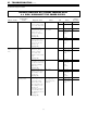
If error “11” or “71” is displayed, check the main gas solenoid
valve.
a. # Disconnect the main gas solenoid valve (SV0)
connector and measure the resistance at the solenoid
terminals.
Normal: 1.7 ~ 2.1 K Ω
If normal, check b below.
Faulty: Replace gas valve.
(Service Procedure IGI-9, page 52)
b. Measure voltage at the main gas solenoid (SV0)
Pink and black wires.
Normal: 80 ~ 100 VDC
If normal, proceed to check item 7 below.
Faulty: Replace PCB unit.
(Service Procedure IGI-2, page 49)
If error “11” or “71” is displayed, check the change over
solenoid (SV1).
a. # Disconnect the change over solenoid (SV1)
connector, and measure resistance at the solenoid
terminals.
Normal: 1.7 ~ 2.1 K Ω
If normal, check b below.
Faulty: Replace the gas valve.
(Service Procedure IGI-9, page 52)
b. Measure voltage at the change over solenoid
(SV1) yellow ~ black wires.
Normal: 80 ~ 100 VDC
If normal, check 8 below.
Faulty: Replace PCB unit.
(Service Procedure IGI-2, page 49)
If error “11” or “71” is displayed, check the change over
solenoid (SV2).
a. # Disconnect the changeover solenoid (SV2) connector,
and measure the resistance at the solenoid terminals.
Normal: 1.7 – 2.1 K Ω
If normal, check b below.
Faulty: Replace the gas valve.
(Service Procedure IGI-9, page 52)
b. Measure the voltage at the changeover solenoid (SV2),
blue – black wires.
Normal: 80 – 100 VDC
If normal, check 9, on next page.
Faulty: Replace the PCB unit.
(Service Procedure IGI-2, page 49)
6) Is the main gas solenoid valve (SV0) operating normally?
7) Is the change over solenoid (SV1) operating normally?
8) Is the change over solenoid (SV2) operating normally?
VI - TROUBLESHOOTING (cont.)
B
EFORE CARRYING OUT CHECKS MARKED WITH A # SIGN, DISCONNECT THE POWER SUPPLY.