
Install Instructions
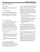
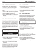
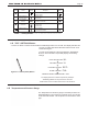
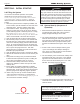
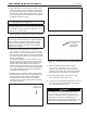
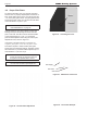
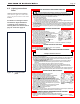

Table Of Contents
- Cover
- TABLE OF CONTENTS
- SECTION 1 GENERAL INFORMATION
- SECTION 2 LOCATING THE BOILER
- SECTION 3 AIR AND VENTING
- SECTION 4 GAS CONNECTIONS
- SECTION 5 PUMP REQUIREMENTS
- SECTION 6 WATERCONNECTIONS
- SECTION 7 ELECTRICAL AND WIRING DIAGRAMS
- SECTION 8 THE DIGITAL DASHBOARD
- SECTION 9 INITIAL STARTUP
- SECTION 10 MAINTENANCE
- SECTION 11 OPERATING DETAILS AND TROUBLESHOOTING
- SECTION 12 REPLACEMENT PARTS

Page 39
1. Set the thermostat to lowest setting.
2. Turn off all electric power to the appliance if service is to be performed.
3. Turn gas control knob clockwise to “OFF”.
1. STOP! Read the safety information above on this label.
2. Set the thermostat to lowest setting.
3. Turn off all electric power to the appliance.
4. This appliance is equipped with an ignition device which
automatically lights the pilot. Do not try to light the pilot by hand.
5. Turn gas control knob clockwise to “OFF”.
6. Wait five (5) minutes to clear out any gas. Then smell for gas,
including near the floor. If you smell gas, STOP! Follow “B” in
the safety information above (to the left) on this label. If you
don't smell gas, go to next step.
7. Turn gas control knob counterclockwise to “ON”.
8. Set thermostat to desired setting.
9. Turn on all electric power to the appliance.
10. If the appliance will not operate, follow the instructions “To Turn Off Gas To Appliance” and call your
service technician or gas supplier.
Honeywell
Gas Valve
VR8304
WARNING: If you do not follow these instructions exactly, a fire or explosion
may result causing property damage, personal injury or loss of life.
A. This appliance is equipped with an ignition device which automatically lights the pilot. Do not try to light the
pilot by hand.
B. BEFORE OPERATING smell all around the appliance area for gas. Be sure to smell next to the floor
because some gas is heavier than air and will settle on the floor.
WHAT TO DO IF YOU SMELL GAS
• Do not try to light any appliance.
• Do not touch any electric switch; do not use any phone in your building.
• Immediately call your gas supplier from a neighbor's phone. Follow the gas supplier's instructions.
• If you cannot reach your gas supplier, call the fire department.
C. Use only your hand to push in or turn the gas control knob. Never use tools. If the knob will not push in or
turn by hand, don't try to repair it, call a qualified service technician. Force or attempted repair may result
in a fire or explosion.
D. Do not use this appliance if any part has been under water. Immediately call a qualified service technician
to inspect the appliance and to replace any part of the control system and any gas control which has
been under water.
Gas Control Shown in
“OFF” Position
1. ARRÊTEZ ! Lisez les instructions de sécurité sur la portion supérieure.
2. Réglez le thermostat à la température la plus basse.
3. Coupez l’alimentation électrique de l’appareil.
4. Cet appareil est muni d’un dispositif d’allumage automatique de
veilleuse. Ne pas tenter d’allumer la veilleuse à la main.
5. Tourner le bouton de commande dans le sens des aiguilles
d’une montre pour le mettre en position d’arrêt “OFF”.
6. Attendre cinq (5) minutes pour laisser échapper tout le gaz. Reniflez
tout le gaz. Reniflez tout autour d l’appareil, y compris près du plancher,
pour déceler une odeur de gaz. Si vous sentez une odeur de gaz,
ARRÊTEZ ! Passez à l’étape “B” des instructions de sécurité sur la
portion supérieure (à gauche) de cette éttiquette. S’il n’y a pas d’odeur
de gaz, passez à l’étape suivante.
7. Tourner le bouton de commande dans le sens contraire des aiguilles
d’une montre pour le mettre en position de marche “ON”.
8. Réglez le thermostat à la température désirée.
9. Mettez l’appareil sous tension.
10. Si l’appareil ne se met pas en marche, suivez les instructions intitulées “Comment couper l’admission de
gaz de l’appareil” et appelez un technicien qualifié ou le fournisseur de gaz.
Soupape de gaz
Honeywell
VR8304
AVERTISSEMENT: Quiconque ne respecte pas à la lettre les instructions dans la
présente notice risque de déclencher un incendie ou une explosion entraînant des
dommages, des blessures ou la mort.
A. Cet appareil est muni d'un dispositif d'allumage qui allume automatiquement la veilleuse. Ne tentez pas
d’allumer la veilleus manuellement.
B. AVANT DE FAIRE FONCTIONNER, reniflex tout autour de l’appareil pour déceler une odeur de gaz. Reniflex
près du plancher, car certains gaz sont plus lourds que l’air et peuvent s’accumuler au niveau du sol.
QUE FAIRE SI VOUS SENTEZ UNE ODEUR DE GAZ
• Ne pas tenter d'allumer d'appareil.
• Ne toucher à aucun interrupteur; ne pas vous servir des téléphones se touvant dans le bâtiment.
• Appelez immédiatement votre fournisseur de gaz depuis un voisin. Suivez les instructions du
fournisseur.
• Si vous ne pouvez rejoindre le fournisseur, appelez le service des incendies.
C. Ne poussez ou tournez la manette d’admission du gaz qu’à la main; ne jamais utiliser d’outíl. Si la
manette reste coincée, ne tentez pas de la réparer; appelez un technicien qualifié. Le fait de forcer la
manette ou de la réparer peut déclencher une explosion ou un incendie.
D. N’utilisez pas cet appareil s’il a été plongé dans l’eau, même partiellement. Faites inspecter l’appareil par
un technicien qualifié et remplacez toute partie du système de contrôle et toute commande qui ont été
plongés dans l’eau.
Bouton de contrôle
du débit en position
d’arrêt “OFF”
FOR YOUR SAFETY READ BEFORE OPERATING
OPERATING INSTRUCTIONS
TO TURN OFF GAS TO APPLIANCE
POUR VOTRE SÉCURITÉ, LISEZ AVANT DE METTRE EN MARCHE
INSTRUCTIONS DE MISE EN MARCHE
COMMENT COUPER L’ADMISSION DE GAZ DE L’APPAREIL
1. Réglez le thermostat à la température la plus basse.
2. Coupez l’alimentation électrique de l’appareil s’il faut procéder à l’entretien.
3. Tourner le bouton de commande dans le sens des aiguilles d’une montre pour le mettre en position
d’arrêt “OFF”.
H0236800D
QTY PART NO. DESCRIPTION
ITEM
NO.
PARTS LIST
11GNITNEV / RIA ,BMOC ,LEBAL0005600H1
1 H2411900 LABEL, WIRING & LOGIC, DIAGRAM, JX 10
9RELLATSNI OT ETON ,GAT0033002H1
8VJ ,REVOC RENRUB ,LEBAL0099620H1
7VJ ,GNINRAW YTEFAS ,LEBAL0079620H1
1 H0269100
LABEL, WARNING, ELECRTRIC SHOCK, CO DETECTOR
6
1 H0236800 LABEL, LIGHTING INSTRUCTIONS, JVS & JX 5
4XJ ,ETALP GNITAR ,LEBAL0034142H1
1 H2415800 LABEL, ENERGYGUIDE, MINI-THERM JX 3
2TFIL TON OD ,LEBAL0095110H1
1XJ ,LEDOM ,LEBAL0092142H1
9.D Lighting Instructions
Decal
Lighting instructions are located on
a label on the right side of the boiler,
and are depicted in this section of the
manual.
For details on starting this boiler
and what the digital dashboard
is showing you as the boiler is
started, please see Sections 8.A on
page 30 and 9.B on page 36
Figure 35. Located on side
panel
MINI-THERM JX Residential Boilers
®