Installation and Operation Instructions Document 1478 Installation and Operation Instructions for MINI-THERM ® JX Residential Gas-Fired Hydronic Boilers Sizes 50-200 MBTU/h FOR YOUR SAFETY: This product must be installed and serviced by a professional service technician, qualified in hot water boiler and heater installation and maintenance. Improper installation and/or operation could create carbon monoxide gas in flue gases which could cause serious injury, property damage, or death.
LAARS Heating Systems TABLE OF CONTENTS SECTION 1 GENERAL INFORMATION 1.A Safety Warnings...................................... 4 1.B Introduction.............................................. 6 1.C Warranty.................................................. 6 1.D Model Number and Nomenclature.......... 6 1.E Model Overview....................................... 7 1.F Dimensions.............................................. 9 1.G The Installation Kit................................. 10 1.
MINI-THERM® JX Residential Boilers 8.C.3 8.C.4 8.C.5 8.C.6 8.D 8.E Manual Reset Low Water Cut-Off.......... 34 Low water Cut-Off ................................ 34 High Limit Differential............................ 34 Restore Factory Default Settings.......... 34 TEST / SETTINGS Button . ................. 35 Temperature and Pressure Gauge..... 35 SECTION 9 INITIAL STARTUP 9.A Filling the System.................................. 36 9.B System Start Up (Seq of Operation)...... 36 9.C Proper Pilot Flame.
LAARS Heating Systems Page 4 SECTION 1 GENERAL INFORMATION 1.A Safety Warnings Safety Warnings are used throughout this manual to bring attention to the presence of hazards with various risk levels and to offer important information concerning the life of this product. There are 3 basic types. 1 WARNING 2 CAUTION 3 Indicates an imminently hazardous situation which, if not avoided, can or will result in death or serious injury and can or will result in catastrophic property damage.
MINI-THERM® JX Residential Boilers Page 5 WARNING WARNING Electrical Shock Hazard Electrical shock can cause severe injury, death or property damage. Disconnect the power supply before beginning installation or changing the wiring to prevent electrical shock or damage to the equipment. It may be necessary to turn off more than one power supply to disconnect.
LAARS Heating Systems Page 6 1.B Introduction 1.D Model Number and Nomenclature This manual provides information necessary for the installation, operation, and maintenance of the LAARS Heating Systems Mini-Therm JX. Read it carefully before starting the installation. All application and installation procedures should be reviewed completely before proceeding with the installation.
MINI-THERM® JX Residential Boilers Page 7 1.E Model Overview Low Loss Header. Models 125 - 200 only 200 MBH 50 MBH Figure 1.
LAARS Heating Systems Page 8 1.E Model Overview (continued) Hydronic Return Hydronic Supply Low Loss Header (sizes 125 - 200) Temp and Pressure Gauges User Control Interface Panel Lock Drain Rating Plate Pressure Relief Valve ‘Knock-outs’ Gas Supply Pressure Relief Valve Main Power 120V Connections See 7.B on page 23 Gas Supply DHW Relay Connections TB3 Field Connections TB1 Field Connections TB2 See 7.D on page 24 Gas Valve Pilot Ignitor Sensor Figure 2.
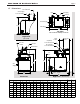
MINI-THERM® JX Residential Boilers Page 9 1.F Dimensions Dimensional Data IN (Return) 1-1/4” NPT Male IN (Return) NPT Male OUT1-1/4” (Supply) 1-1/4” NPT Male 7" OUT (Supply) 18cm 1-1/4” NPT Male 7" 18cm Out Supply PRV Out SupplyIn Return PRV In Return Control Display Control Display F1 F1 T&P Gauge T&P Gauge Low Loss Header & Damper not shown Right View Right(50, View 75, 100) 4-5/8" 4-5/8"11.8cm IN (Return) 11.
LAARS Heating Systems Page 10 1.G The Installation Kit This residential unit is shipped in a single crate with a boxed installation kit that contains these components. 1. 2. 3. I/O Manual Vent Damper Burner Air Baffle Gauge (Mini Gauge) Optional: 1. Circulator pump & flange kit (50 - 100) SECTION 2 LOCATING THE BOILER 1.H Accessory Kits Available See Section 12.C on page 50 for part numbers.
MINI-THERM® JX Residential Boilers SECTION 3 Page 11 Air and Venting 3.A Safety Warnings WARNING This boiler must be vented in accordance with Part 7, Venting of Equipment, of the latest edition of the National Fuel Gas code, NFPA 54/ANSI Z223.1 and all applicable local building codes. In Canada, follow CAN/CGA B149 Installation codes.
LAARS Heating Systems Page 12 3.B Combustion Air Supply The boiler location must provide sufficient air supply for proper combustion, and ventilation of the surrounding area as outlined in the latest edition of U.S. ANSI standard Z223.1 or in Canada, CAN/CGA-B149.1 or .2, and any local codes that may be applicable.
MINI-THERM® JX Residential Boilers Page 13 10 (3.0) OR LESS 2 (0.6) MIN. WALL OR PARAPET CHIMNEY 10 (3.0) OR LESS 2 (0.6) MIN. RIDGE MORE THAN 10 (3.0) 3 (0.9) MIN. 3 (0.9) MIN. TERMINATION 10 FT. (3.0m) OR LESS FROM RIDGE, WALL OR PARAPET 3 (0.9) MIN. CHIMNEY WALL OR PARAPET NOTE: NO HEIGHT ABOVE PARAPET REQUIRED WHEN FROM WALLS OR PARAPET IS MORE THAN 10 FT. (3.0m) Dimensions in feet (m). CHIMNEY MORE THAN 10 (3.0) 10 (3.0) RIDGE 2 (0.6) MIN. 3 (0.9) MIN. CHIMNEY Figure 6.
Page 14 3.D Vertical Venting - Category I All venting must comply with fuel gas code and be installed by a licensed installer. This boiler can be vented into a masonry chimney, (see Figure 4 and Figure 5 on page 12) provided several conditions are met: 1. The chimney must have an appropriate lining that is clean, properly constructed and properly sized. 2. The chimney passage way shall be examined to ascertain that it is clear and free of obstructions. 3.
MINI-THERM® JX Residential Boilers 3.E Locations for Vent Pipe Terminator Page 15 Canadian Installations1 U.S.
LAARS Heating Systems Page 16 3.F Venting with a Power Venter This boiler is certified for use with the manufacturer's suggested Power Venter, which is supplied in a kit that includes Installation Instructions. See the accesories list in the Parts Section of this manual. The location of the venter on the outside wall shall be in accordance with ANSI Z223.1/NFPA 54, or in Canada with CAN/ CGA-B149 and applicable local codes. 3.
MINI-THERM® JX Residential Boilers SECTION 4 Page 17 Gas Connections 4.A Gas Supply and Piping 1. Gas piping installation must be in accordance with the latest edition of ANSI Z223.1 and all local codes. In Canada, the installation must be in accordance with CSA-B149.1 and all local codes that apply. Supply Pressure Natural Gas LP Gas Table 3. Minimum CAUTION Permanent damage to the gas valve will occur if the following procedures are not followed. Maximum 5.5 Inches WC 10.5 Inches WC (1.
LAARS Heating Systems Page 18 NOTE: The boiler and all other gas appliances sharing the boiler gas supply line must be firing at maximum capacity to properly measure the inlet supply pressure. Low gas pressure could be an indication of an undersize gas meter and/or obstructed gas supply line. 8. 9. The correct manifold gas pressure is stamped on the rating plate. The regulator is pre-set at the factory, and normally requires no further adjustment.
100 100 29.3 84 1-1/4 3/4 125 125 36.6 105 31.1 84 1-1/4 3/4 150 150 44.0 126 37.2 84 1-1/4 3/4 200 199 58.3 168 49.2 84 1-1/4 3/4 MINI-THERM JX Residential Boilers ® SECTION 5 84 24.9 Page 19 PUMP REQUIREMENTS Water Requirements 5.AFlow Pump Sizing Temperature Rise 15°F 8°C Size Flow Rate 20°F 11°C Headloss Flow Rate 25°F 14°C Headloss Flow Rate Headloss gpm l/s ft m gpm l/s ft m gpm l/s ft m 50 5.3 0.3 0.3 0.1 4.0 0.3 0.2 0.1 3.2 0.2 0.
Page 20 LAARS Heating Systems SECTION 6 WATER CONNECTIONS 6.A Water Piping NOTE: This boiler must be installed in a closed pressure system with a minimum of 12 psi (82.7kPa) static pressure at the boiler. Section 6.F on page 21 shows ‘typical’ plumbing installations. Be sure to provide unions and isolation valves at the boiler inlet and outlet so it can be isolated for service. Check local codes for specific plumbing requirements before beginning the installation.
MINI-THERM® JX Residential Boilers 6.F Page 21 Typical Plumbing Diagrams These diagrams are only meant as a guide. All components or piping required by local code must be installed.
LAARS Heating Systems Page 22 Typical Plumbing Diagrams (continued) Check Valves Air Scoop Valves Zone Pumps (must be sized properly) Pump Valves Valves Check Valve Low Loss Header w/ Pump Indirect Tank JX Figure 13. Low Loss Header with Zone Pumps and DHW Low Loss Header is standard on models 125, 150, and 200 and Optional for models 50, 75, and 100. Air Scoop Valves Zone Valves Pump Pump Valves Valves Low Loss Header w/ Pump JX Check Valve Indirect Tank Figure 14.
ow Input Size MBTU/h kW Nat Gas MBTU/h kW % M50 INI-THERM JX Residential 50 14.7 42 12.6 Boilers 84 ® Conn. Conn. in. in. 1-1/4 3/4 75 75 22.0 63 18.8 84 1-1/4 3/4 100 100 29.3 84 24.9 84 1-1/4 3/4 150 Safety 150 Warnings 44.0 126 7.A 37.2 84 1-1/4 3/4 168 49.2 WARNING 84 1-1/4 3/4 SECTION 7 125 125 199 200 ELECTRICAL AND 84 WIRING DIAGRAMS 36.6 105 31.1 1-1/4 3/4 58.
LAARS Heating Systems Page 24 7.D Field Connections This boiler has three Field Connection Terminals. TB1, TB2 and TB3 (TB3 is for optional equipment). TB1 -TT, DHW, OAS TB2 -Pumps and Aux Power Open Closed TB3 -DHW Relay Connections (optional) Figure 15. Terminal Block Locations 7.D.1 Figure 16. Unlocking the Cover TB1 (Terminal Block 1 -TT, DHW, OAS) 7.D.1.a TT (Central Heat) TT is for the end switch of a zone relay control system or direct thermostat connection.
MINI-THERM® JX Residential Boilers 7.D.2 Page 25 TB2 (for pumps and aux power) 7.D.2.a Boiler Pump This terminal and the 120V(N) terminal will provide power to the boiler pump whenever the boiler is running. Use this to power the Low Loss Header (LLH) pump. If not using a LLH then this terminal can run power for a single zone or a zone valve system pump. 7.D.2.b SYS Pump This terminal and the 120V(N) terminal will provide power to zone pumps or a zone valve system pump.
LAARS Heating Systems Page 26 Example: Laars Power Kit Air Wiring to JX 7.E Wiring Connections, Power VentVent and Figure 17. - Power Vent Kit Wiring example L N 1 2 4 Example: Fields Controls CAS-4 Wiring to JX Laars Power Vent Kit Example: Fields Controls CAS-4 Wiring to JX Example:Typical Fields Controls CAS-4 Wiring to JXto JX for Anti-condensing protection Example: Zone Pump Control Wiring L1 N Figure 18.
L N MINI-THERM® JX Residential Boilers 1 2 4 Laars Power Vent Kit Page 27 Example: Typical Zone Pump Control Wiring to JX for Anti-condensing protection NOTE: Must have a dedicated boiler pump (such as LLH) when using this method. Figure 20. - Typical Zone Pump Control Wiring for Anti-condensing protection Example: Typical Zone Valve Control Wiring to JX for Anti-condensing protection. Zone Pump NOTE: Must have a dedicated boiler pump (such as LLH) when using this method. Figure 21.
LAARS Heating Systems Page 28 7.F Wiring Diagram CUSTOMER POWER CONNECTION 120VAC SYS PUMP AUX POWER NEUTRAL BOILER PUMP TRANSFORMER P1 24VAC R Y A Y R P2 R R O Y O OAS COM PV4 WWSD PV1 24V(-) PV2 FIELD INTERLOCK DHW TT A O O R DHW Y W SD W OM C S OA R DAMPER CONNECTOR Y R Y X4 Boiler Controller X2 R BLOCKED VENT SWITCH ROLL OUT SWITCH GAS VALVE 24V (N) Y O S R PILOT VALVE 24V (L) O X1 MAIN VALVE 24V (L) FACTORY INSTALLED JUMPERS: Figure 22.
MINI-THERM® JX Residential Boilers Page 29 7.
LAARS Heating Systems Page 30 SECTION 8 HE DIGITAL T DASHBOARD This boiler is ready to go ‘Out of the Box’ and into a typical single loop installation with a preset outlet water temperature of 190°F. Other than the basic installation and connecting the TT (Call for Heat) there is no further setup needed at the Digital Dashboard. If you are installing a more advanced heating and/or DHW system, you will need to use the Economy, Hi Limit, and Lo Limit Dials. See Sections 8.A.1 and 8.A.2 8.
Decimal lights on a call for heat. MINI-THERM® JX Residential Boilers my (OFF or LO, 1, 2, 3, 4, 5, HI) Factory: 1 Indicator Light (announces heat call) *Model specific Page 31 Control, Digital and Ignition L E D s differential en the econd off. See n page 9. The Ignition LED’s light in sequence ture (see “How Thermal Targeting Works” on page 6). If the heating system is unable to supply needed heat to the house, the ECONOMY Dial should be turned to a lower setting (exLEDs light in sequence.
LAARS Heating Systems Page 32 Ignition LED's (continued) 8.A.6.d FLAME Illuminates when the pilot flame is lit. If pilot flame is not sensed within 75 seconds or if flame is lost the LED will blink. 8.B Default Settings This boiler is ready to go ‘Out of the Box’ and into a typical single loop installation with a preset temp at 190°F. If installing a more complex system, Advanced Settings will allow you to adjust the system control to provide improved performance. 8.C Advanced Settings 8.C.
MINI-THERM® JX Residential Boilers Page 33 8.C.1.c Thermal Boost To ensure that the heating system always satisfies a call for heat, the control is equipped with a thermal boost feature. If the thermostat is not satisfied thirty minutes after the boiler reaches the reset temperature, the control will boost the reset temperature by 10 degrees. It will continue to boost at 30 minute intervals until the call is satisfied.
LAARS Heating Systems Page 34 8.C.2 Degrees Fahrenheit or Celsius The control has the ability to operate in degrees Fahrenheit or Celsius. When operating in Celsius, a c will appear in the display next to the temperature whenever the temperature is below 100 degrees. To change between degrees Fahrenheit and degrees Celsius. 1. Turn the LO TEMP dial to access the Program Mode – indicated in the display as Pro See Figure 27 on page 35. 2. Turn the HI TEMP dial to select feature 2. 3.
Dial Setting Feature Options Default Setting Description ® MINI-OPTIONAL THERM JX orResidential Boilers Degrees Fahrenheit Fahrenheit Celsius 2 FEATURES continuedF 3 Dial Setting 4 2 6 3 7 4 8 c Degrees Celsius LWCO Manual or Automatic Reset Feature Not available on this control Fahrenheit or Celsius Not available on this control LWCO Manual or Automatic Reset A b Options Automatic Reset Manual Reset Not available Low Water Cut-Off on Function this control on OFF Page 35 F A Default Setting
LAARS Heating Systems Page 36 SECTION 9 INITIAL STARTUP 9.A Filling the System It is crucial to the efficient operation of the system that all air be removed from the circuit. For this reason, an air scoop and vent should be located close to the boiler outlet, and there should be a minimum distance between cold water feed and air elimination system. 1. When the system has been completely installed, and is free of leaks, open all automatic air vents and close all manual vents.
MINI-THERM® JX Residential Boilers Page 37 6. W hen pilot flame is sensed the green “flame” LED will turn on. If flame is not sensed in 75 seconds the pilot valve will de-energize, the spark will terminate, and the green “flame” LED will blink. After a 5 minute delay the sequence will retry at step 5. There will be an unlimited number of retries. NOTE: Check for good quality pilot flame. See Section 9.C on page 38. NOTE: Check the flame current and make the necessary adjustments to the pilot valve.
LAARS Heating Systems Page 38 9.C Proper Pilot Flame To view the pilot flame, the cover must be unlocked and removed. A properly adjusted pilot should have a blue, steady flame with an inner cone that engulfs 3/8” - 1/2” of the pilot ignitor sensor. The pilot ignitor sensor should glow bright orange from the heat and the flame current should be 1.0 μA to 1.8 μA. Open Closed NOTE: To read flame current see Section "8.
MINI-THERM® JX Residential Boilers 9.D L ighting Instructions Decal Page 39 FOR YOUR SAFETY READ BEFORE OPERATING WARNING: If you do not follow these instructions exactly, a fire or explosion may result causing property damage, personal injury or loss of life. Lighting instructions are located on a label on the right side of the boiler, and are depicted in this section of the manual.
LAARS Heating Systems Page 40 9.E System Shutdown 1. 2. 3. 4. Turn off the main electrical disconnect switch. Close all manual gas valves. If you think the unit might freeze, drain it. All water must be removed from the heat exchanger, or damage from freezing may occur. To completely drain the boiler, first drain the right side by opening the boiler drain. Then remove the PRV and related fittings. Then remove the top and left side panels.
MINI-THERM® JX Residential Boilers 10.A.3 Side Panel Removal Remove the front access and the top as described previously. Drain the boiler and remove the drain valve and/or the PRV and associated fittings depending on the panel being removed. Then pull upward and inward slightly at the top inside flanges. These are spring type latches which will release as force is applied upward.
Page 42 LAARS Heating Systems 10.B Maintenance 1. L ubricate any motor bearings that are not sealed bearings per the instructions. 2. I f a strainer is employed in a pressure reducing valve or the piping, clean it every six months or as needed. 3. A t start-up, and periodically thereafter, the burner and pilot flames should be observed. If the flame has the appearance of “sooting” tips, check for debris near the orifices.
MINI-THERM® JX Residential Boilers Page 43 SECTION 11 Operating Details and Troubleshooting 11.A Operating Details When power is turned on, the digital display will indicate the Boiler Outlet Temperature. If a demand for heat is received from a room thermostat or a tank aquastat (if provided) the third decimal LED, located at the lower right of the last temperature digit, will illuminate to indicate that a call for heat has been received and the startup has been initiated. See Section 9.B for details.
LAARS Heating Systems Page 44 11.C Troubleshooting Table # Symptom Cause Remedy 1 Boiler Pump not operating No power . . . . . Pump defective . . . . . Incorrectly wired . . . . . Check circuit breakers and power source. Replace. Recheck wiring diagrams (System pump will not work if below 160ºF or if DHW call) 2 Pilot outage Inlet gas pressure too low . . . . . Consult gas utility company. Inlet gas pressure to boiler should be 5.5" (1.4 kPa) to 9.0" (2.2 kPa) water column on natural gas. 10.
MINI-THERM® JX Residential Boilers 11.C.1 Page 45 Troubleshooting Flow Chart 1 (burners off) Is the Green LED (TEMP ACTIVE) On? NO The Control is Not Powered. The Temp Active LED will be on at all times when the control is powered. Check for 120 VAC on the control input. YES CAUTION – ALWAYS ALLOW A BOILER TO COOL BEFORE ADDING WATER Is the Red LED (LOW WATER) On? The burner will not fire until the low water condition is satisfied. YES Check that the system is filled with water.
LAARS Heating Systems Page 46 Troubleshooting Flow Chart 2 – Burner Will Not Shut Down 11.C.2 Troubleshooting Flow Chart 2 (burners on) Is the Red LED (LOW WATER) On? YES The Control is Sensing Low Water. TURN OFF POWER TO BURNER IMMEDIATELY! NO Is either Yellow LED On? WARNING WARNING! CAUTION – ALWAYS ALLOW A BOILER TO FULLY COOL BEFORE ADDING WATER. YES The Control has Reached Target or High Limit Temperature. YES The Control is Operating Normally. Recheck wiring.
MINI-THERM® JX Residential Boilers Page 47 SECTION 12 REPLACEMENT PARTS 12.A Parts Illustrations A1 Reference to 12.B Parts List starting on next page.
LAARS Heating Systems Page 48 REV 1 CA0194 SH D2 THIS DOCUMENT AND THE INFORMATION CONTAINED HEREIN ARE PROPRIETARY TO LAARS HEATING SYSTEMS AND SHALL NOT BE REPRODUCED, TRANSFERED TO OTHER DOCUMENTS, USED OR DISCLOSED TO OTHERS FOR MANUFACTURING OR ANY OTHER PURPOSE EXCEPT AS SPECIFICALLY AUTHORIZED IN WRITING BY LAARS HEATING SYSTEMS. REV.
50 75 100 125 150 200 Page 49 HERM® JX Residential Boilers AMINIJacketTComponents A1 Panel, Top, Front R5X3032 R7X3032 R10X3032 R12X3032 R15X3032 R20X3032 50 75 100 125 150 200 A2 Panel, Left Side R5X3043 R5X3043 R5X3043 R5X3043 R5X3043 R5X3043 A Jacket Front Components A3 Panel, 5X3038 7X3038 10X3038 12X3038 15X3038 20X3038 A1 Panel,Cover Top, Front R5X3032 R7X3032 R10X3032 R12X3032 R15X3032 R20X3032 A4 Front R5X3045 R7X3045 R10X3045 R12X3045 R15X3045 R20X3045 12.
O‐Ring (Pump) ‐ ‐ ‐ S2138700 S2138700 S2138700 A7 Draft Diverter Assembly 5X3030 7X3030 10X3030 12X3030 15X3030 20X3030 Air Shutter, Burner L0055900 L0055900 L0055900 L0055900 L0055900 L0055900 Seal (Flange) ‐ ‐ ‐ S2137800 S2137800 S2137800 A8 Panel, Rear (not shown) Note: For complete 5X3031 7X3031 10X3031 15X3031 20X3031 Main Top, Gas Orifice conversion kits (LP or Nat all altitudes available)12X3031 see accessory section.
MINI-THERM® JX Residential Boilers Page 51 12.D Glossary of Terms Air Vent A device used to purge air from the Circuit. Should be located at the highest point in the Circuit. Branch The section(s) of supply and return piping, including the heat distribution units connected directly to the trunk. Also referred to as a “zone”. Circuit Entire water circulation piping, beginning and ending at the boiler (Series Loop System).
MINI-THERM JX Residential Boilers Notes: All Manuals (Install & Operate, Start Up, and Service Manuals) can be downloaded at www.laars.com For LAARS Product and Service VIDEOS h t t p s : / / w w w. y o u t u b e . com/user/LaarsHeating H2411200- Dimensions and specifications subject to change without notice in accordance with our policy of continuous product improvement. Customer Service and Product Support: 800.900.9276 • Fax 800.559.