
Install Instructions
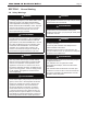
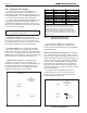
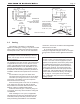

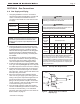
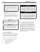

Table Of Contents
- Cover
- TABLE OF CONTENTS
- SECTION 1 GENERAL INFORMATION
- SECTION 2 LOCATING THE BOILER
- SECTION 3 AIR AND VENTING
- SECTION 4 GAS CONNECTIONS
- SECTION 5 PUMP REQUIREMENTS
- SECTION 6 WATERCONNECTIONS
- SECTION 7 ELECTRICAL AND WIRING DIAGRAMS
- SECTION 8 THE DIGITAL DASHBOARD
- SECTION 9 INITIAL STARTUP
- SECTION 10 MAINTENANCE
- SECTION 11 OPERATING DETAILS AND TROUBLESHOOTING
- SECTION 12 REPLACEMENT PARTS

Page 19
Table 5. Water Flow Requirements and Temperature Rise
Water Flow Requirements
Electrical
Data
All Sizes
with
Low Loss Header without Low Loss Header
Voltage 120 V 120 V
FLA .70 A .20 A
MCA .9 A .25 A
MOP 15 A 15 A
Minimum Clearances
Left + Right Sides Front Flue and Rear Top
Size inches cm inches cm inches cm inches cm
ALL 4 10 2 5 6 15 20 51
Minimum
Clearances
from
Adjacent
Construction
Temperature Rise
15°F 8°C 20°F 11°C 25°F 14°C
Size Flow Rate Headloss Flow Rate Headloss Flow Rate Headloss
gpm l/s ft m gpm l/s ft m gpm l/s ft m
50 5.3 0.3 0.3 0.1 4.0 0.3 0.2 0.1 3.2 0.2 0.1 0.1
75 8.0 0.5 0.6 0.2 6.0 0.4 0.3 0.1 4.8 0.3 0.2 0.1
100 10.7 0.7 1.3 0.4 8.0 0.5 0.7 0.2 6.4 0.4 0.5 0.2
125
*
13.3 0.8 2.2 0.7 10.0 0.6 1.3 0.4 8.0 0.5 0.8 0.2
150
*
17.0 1.1 2.5 0.8 12.8 0.8 1.8 0.5 10.3 0.6 1.2 0.4
200
*
22.8 1.4 5.0 1.5 17.0 1.0 3.1 0.9 13.7 0.9 1.9 0.6
*Models 125-200 ship with a low loss header with integral pump, so a separate boiler pump does not need to be sized or fi eld-supplied.
NOTES:
1. Shaded area represents typical temperature rise.
2. gpm = water fl ow in gallons per minute.
3. l/s = water fl ow in liters per second.
4. ft = pressure drop (headloss) through the boiler in feet of water.
5. m = pressure drop (headloss) through the boiler in meters of water.
Sizing
Data
Heating Capacity AFUE % Water Gas
Input Nat Gas Conn. Conn.
Size MBTU/h kW MBTU/h kW % in. in.
50 50 14.7 42 12.6 84 1-1/4 3/4
75 75 22.0 63 18.8 84 1-1/4 3/4
100 100 29.3 84 24.9 84 1-1/4 3/4
125 125 36.6 105 31.1 84 1-1/4 3/4
150 150 44.0 126 37.2 84 1-1/4 3/4
200 199 58.3 168 49.2 84 1-1/4 3/4
SECTION 5 PUMP REQUIREMENTS
5.A Pump Sizing
Table 6. Equivalent Feet and Head Loss
Model
Size
GPM
Equivalent Feet
of ¾” Type M
Copper
Feet of Head
Loss
50 5
75 4.9
100 6.5
75 7.5
75 10.3
100 13.8
100 10
75 17.6
100 23.5
MINI-THERM JX Residential Boilers
®
This boiler has a water tube design, and requires
correct water ow for proper operation and long life.
Models 125-200 are built with a low loss header with
integral pump that serves the boiler and ensures proper
water ow. Optional low loss header with integral pump
kits, or kits with just pumps, are oered for use with
models 50, 75 and 100. When neither of the optional
kits are used with models 50, 75 and 100, care must be
taken to choose pumps and in the design of the piping.
A typical residential pump can ow enough water for the
average, properly-designed, zone system for models 50
and 75. If a zone exceeds 100 equivalent feet of 3/4”
pipe, a pump may not be large enough to overcome the
resistance and ensure proper water ow through the
boiler.
Sizing the pump requires the headloss of the zone
piping combined with the heat exchanger headloss.
Use Table 5 and 6 to approximate the head loss for
each zone and ensure the pump selection is adequate.
Compare to the manufacturer's pump curve to ensure
sucient ow for the boiler.
Primary/Secondary systems and boilers with LLH
systems can be used to avoid needing larger pumps.
The boiler pump will maintain the proper ow
through the boiler regardless of the ow through the
system. This means that the system ow is now
only critical to the building comfort not the boiler
safety. Headloss is only calculated through the
individual zones for sizing of the system pump(s).