
Install Instructions
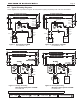

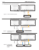
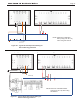


Table Of Contents
- Cover
- TABLE OF CONTENTS
- SECTION 1 GENERAL INFORMATION
- SECTION 2 LOCATING THE BOILER
- SECTION 3 AIR AND VENTING
- SECTION 4 GAS CONNECTIONS
- SECTION 5 PUMP REQUIREMENTS
- SECTION 6 WATERCONNECTIONS
- SECTION 7 ELECTRICAL AND WIRING DIAGRAMS
- SECTION 8 THE DIGITAL DASHBOARD
- SECTION 9 INITIAL STARTUP
- SECTION 10 MAINTENANCE
- SECTION 11 OPERATING DETAILS AND TROUBLESHOOTING
- SECTION 12 REPLACEMENT PARTS

Page 27
Figure 20. - Typical Zone Pump Control Wiring for
Anti-condensing protection
Figure 21. - Typical Zone Valve Control Wiring for
Anti-condensing protection.
NOTE: Must have a dedicated boiler
pump (such as LLH) when using
this method.
L N 1 2 4
Example: Laars Power Vent Kit Wiring to JX
Laars Power Vent Kit
Example: Typical Zone Pump Control Wiring to JX for Anti-condensing protection
Example: Typical Zone Valve Control Wiring to JX for Anti-condensing protection.
Zone Pump
MINI-THERM JX Residential Boilers
®
NOTE: Must have a dedicated
boiler pump (such as LLH)
when using this method.