
Install Instructions
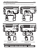

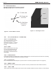


Table Of Contents
- Cover
- TABLE OF CONTENTS
- SECTION 1 GENERAL INFORMATION
- SECTION 2 LOCATING THE BOILER
- SECTION 3 AIR AND VENTING
- SECTION 4 GAS CONNECTIONS
- SECTION 5 PUMP REQUIREMENTS
- SECTION 6 WATERCONNECTIONS
- SECTION 7 ELECTRICAL AND WIRING DIAGRAMS
- SECTION 8 THE DIGITAL DASHBOARD
- SECTION 9 INITIAL STARTUP
- SECTION 10 MAINTENANCE
- SECTION 11 OPERATING DETAILS AND TROUBLESHOOTING
- SECTION 12 REPLACEMENT PARTS

Page 30
This boiler is ready to go ‘Out of the Box’ and into a
typical single loop installation with a preset outlet water
temperature of 190°F. Other than the basic installation
and connecting the TT (Call for Heat) there is no further
setup needed at the Digital Dashboard.
If you are installing a more advanced heating and/or
DHW system, you will need to use the Economy, Hi
Limit, and Lo Limit Dials. See Sections 8.A.1 and 8.A.2
IMPORTANT: This boiler is equipped with a
feature that saves energy by reducing the boiler
water temperature as the heating load decreases.
This feature is equipped with an override which is
provided primarily to permit the use of an external
energy management system that serves the same
function. THIS OVERRIDE MUST NOT BE USED
UNLESS AT LEAST ONE OF THE FOLLOWING
CONDITIONS IS TRUE:
• An external energy management system is installed
that reduces the boiler water temperature as the
heating load decreases.
• This boiler is not used for any space heating.
• This boiler is part of a modular or multiple boiler
system having a total input of 300,000 BTU/hr or
greater.
• This boiler is equipped with a tankless coil.
SECTION 8 THE DIGITAL
DASHBOARD
The Current Status of the boiler is displayed by the
various indicators along the top of the Dashboard
8.A.1 Setting the Economy Feature
The economy feature is factory set for a 1 zone
heating system. To adjust, turn the economy dial until
the number display equals the number of heating
zones. The economy feature conserves fuel by
setting varying target temperatures based on system
conditions, over-riding standard limit settings.
8.A.2 High Limit (High Temp)
The high limit is factory set at 190ºF. To adjust, turn
the HI TEMP dial until the desired setting is displayed.
(Range: 160º - 220ºF)
8.A.3 Low Limit (Advanced Options / Adjust)
Low Limit is not applicable to the JX, but this knob
does have functionality for Advanced Options.
8.A.4 Control LEDs
8.A.4.a ACTIVE (TEMP)
Indicates that the control is powered and that the
temperature function is active.
8.A.4.b HI TEMP
Illuminates when the boiler water temperature reaches
the high limit setting. It will remain below it’s dierential
setting. The Control prevents burner operation while
this LED is on.
8.A.4.c ACTIVE (LWCO)
Indicates that the low water cut-o (LWCO) function of
the Control is active.
IMPORTANT: If the control is installed with a
well other than the Electro-Well, this LED will not
illuminate indicating that the control is not providing
low water cut-o functionality.
8.A.4.d LOW WATER
Indicates that the boiler is in a low water condition.
The control will prevent burner operation during this
condition. If the LOW WATER light is blinking, the
control has been programmed to provide lockout
protection in the event a low water condition is
detected. Pressing the TEST/SETTINGS button will
reset the control. IMPORTANT: The system must be
checked by a qualied heating professional prior to
resuming operation. See 8.C.3 on page 34 for more
info.
8.A Getting to know the Digital Dashboard.
The digital dashboard for the controller is protected by a
removable clear plastic cover. See Figure 24.
Figure 24. Remove the Cover. Return when Finished
Under the removable clear cover, there are three dials and
a test button. See Figure 25 on page 31 and Figure 27
on page 35.
WARNING
Dry your hands before removing the cover and
touching the dials or the test button. ALWAYS place
the cover back into it's original position when you have
completed your adjustments.
LAARS Heating Systems