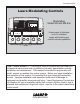
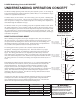
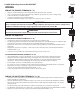
Document 4211A Laars Modulating Controls M4 Modulating Model M4 and M4-Ext Mini-MOD FULLModulation MODULATION SEQUENCING Full Sequencing Control SYSTEM OUTPUT RATINGS: 120VAC, 6A RESISTIVE 1A PILOT DUTY, 15A TOTAL FOR ALL CIRCUITS A INPUT RATINGS: B 115VAC 60Hz , 30VA MAX --- --- C USE COPPER WIRE, CLASS 1 WIRE ONLY. D ENCLOSED ENERGY MANAGEMENT EQUIPMENT LISTED 99RA CAUTION: RISK OF ELECTRIC SHOCK More than one disconnect switch may be required to de-energize the equipment before servicing.
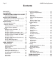
Page 2 LAARS Heating Systems Contents M4 LAYOUT . . . . . . . . . . . . . . . . . 3 M4 OVERVIEW . . . . . . . . . . . . . . . 4 UNDERSTANDING OPERATION CONCEPT 5 Reset Ratio/Outdoor Reset . . . . . . . . . . 5 INITIAL PILOT PROGRAM . . . . . . . . Making Sure You Have the Right Control Selecting the System Features. . . . . . INSTALLATION . . . . . . . . . . . . . . Mounting the Enclosure . . . . . . . . . Install the Sensors . . . . . . . . . . . . . . . . . .
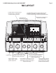
LAARS Modulating Controls M4 & M4-EXT Page 3 M4 LAYOUT Program Switch to restrict access to function changes. This switch is covered with Wiring Enclosure. The digital display shows the system status, set point, lead stage , and status of each stage. To view and adjust settings, press the appropriate buttons. Buttons function is presented on Bottom Row of display. LED indicates the associated relay status.
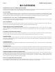
Page 4 LAARS Heating Systems M4 OVERVIEW SEQUENCES UP TO 4 FULLY MODULATING STAGES. The M4 is the perfect control whenever multiple fully modulating stages are required for hydronic heating applications. The M4 controls the on/off and the modulation of each stage to maintain precise system set point control. PID TYPE LOGIC The M4’s control algorithms allow it to look at the rate of change in the system.
LAARS Modulating Controls M4 & M4-EXT Page 5 UNDERSTANDING OPERATION CONCEPT The M4 also controls the system circulating pump with an adjustable Outdoor Cutoff. When the outdoor temperature is above Outdoor Cutoff, the pump is off and no heating water is circulated through the system. When the outdoor temperature drops below the Outdoor Cutoff, the system pump relay is activated and the heating water circulates through the system.
Page 6 LAARS Heating Systems MAKE SURE YOU HAVE THE RIGHT CONTROL If you need the M4 to do additional tasks that either are not listed or do not know how to configure them, contact LAARS. INITIAL SETUP Setting an Initial Program will ease the configuration of the M4 and will give the opportunity to utilize many of the energy saving features and give more comfortable heat when needed.
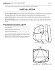
LAARS Modulating Controls M4 & M4-EXT Page 7 System Run-On • This feature lets the M4 run the SYS relay for a longer period after the boilers have been turned off. When this relay is used to control a pump, it helps in dissipating the excess heat from the boilers combustion chamber. INSTALLATION Each of the M4 or M4-Extension consists of three primary enclosure components. • The Enclosure Display Module: contains the display, buttons, LEDs and electric wiring terminals.
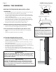
Page 8 LAARS Heating Systems INSTALL THE SENSORS Immersion Heating System Sensor Immersion Well 3/8" ID 1/2" NPT Common Supply Pipe HEATING SYSTEM SENSOR (HSS) INSTALLATION LOCATING HSS • Put the Heating System sensor approximately 10' feet past the last boiler on the common supply header but before any major takeoffs. • The sensor must be located where it sees the output of all the boiler stages.
LAARS Modulating Controls M4 & M4-EXT Page 9 WIRING PWR L N Bring the 120VAC 60Hz power wires through the bottom Knockout of the enclosure. Class 1 voltages must enter the enclosure through a different opening from any Class 2 voltage wiring. Connect the hot line to terminal marked L. Connect the neutral line to the terminal marked N. LAARS recommends installing a surge suppressor on the power source to the M4.
Page 10 LAARS Heating Systems WIRING THE PROVE (TERMINALS 29, 30) • • • • • The Prove feature is provided to check system component operation and must be selected in the Startup Menu. A typical use of this feature is to check for flow before firing any boiler. If the PROVE input is open on a call, the M4 will enable only the System Output. All Boiler outputs will be off when the PROVE input is open. A factory-installed jumper provides the System Prove signal.
LAARS Modulating Controls M4 & M4-EXT WIRING TO MODULATING MOTORS Page 11 A B CUR / VLT CUR / V WIRING TO 4-20MA MODULATING MOTORS (A TERMINALS 13, 14), (B TERMINALS 16, 17), ... • The M4 can be equipped to operate up to four 4-20 mA modulating motors. • The M4-Extension can be equipped to operate up to six 4-20 mA modulating motors. • The M4 and the M4-Extension sources 24VDC excitation voltage for the 4-20mA signal.
Page 12 LAARS Heating Systems MENU SEQUENCE ------------- SEASON -------------Winter Summer SAVE BACK 70 (START) to continue START BACK ------------- WARNING -----------THESE SETTINGS CHANGE PRIMARY SYSTEM FUNCTIONS.
LAARS Modulating Controls M4 & M4-EXT Page 13 ---------------- GAIN -------------- ----------- SETTINGS -----------Season Winter Set Point 70 F BACK SELECT -------- LEAD ROTATION ------Manual Time Last-On SYSTEM SETTINGS2 -- OUTDOOR SENSOR TRIM ---- [ +0 F BACK ] BACK SELECT -------------- SETBACK ----------- SAVE --- SYSTEM SENSOR TRIM ---- [ ---------- SETTINGS 2 ---------Standby Time 10min System Run-On 0min Setback 0 F Last St
Page 14 STARTUP SETTINGS LAARS Heating Systems CAUTION A good practice after performing any Startup menu modifications is to check all operating settings and adjustments to match the new settings. PROGRAM CHANGE SETTINGS To be able to change the M4 settings the Program/Run Switch must be set to Program. The switch is located under the Enclosure Wiring Cover for security. The Enclosure Wiring Cover can be securely closed using a lock.
LAARS Modulating Controls M4 & M4-EXT SELECTING THE MODULATING MODE Normal, Parallel Default: Normal Button: MENU//..../Modulating Mode • Some boilers run more efficiently as their modulation increases. For these units, it is more energy efficient to run one unit in high than several units at lower modulation. If your units are of this type, select Normal. This is the recommended setting for typical steel and cast iron boilers.
Page 16 LAARS Heating Systems RESET MODE • When All-On is selected, the M4 will turn all boilers On to a 100% when System reads Short or Open and Outdoor is below Outdoor Cutoff. When Outdoor reads Short or Open, the M4 will turn all boilers On to a 100%. • When All-Off is selected, the M4 will turn all boilers Off when either System or Outdoor sensor reads Short or Open. SET POINT MODE • When All-On is selected, the M4 will turn all boilers On to a 100% when the System sensor reads Short or Open.
LAARS Modulating Controls M4 & M4-EXT • With most baseboard heating applications, a 1.00 (OD):1.00 (SYS) setting is a good place to start. With a 1.00 (OD):1.00 (SYS) ratio, for every degree the outside temperature falls, the system water temperature is increased one degree. If required: Adjust the RESET RATIO in cold weather. If the ambient building temperatures are too cold in cold weather, move the ratio to a higher selection. That is, if 1.00 (OD):1.
Page 18 LAARS Heating Systems MAXIMUM WATER TEMP --- MAXIMUM WATER TEMP ---- Adjustable 90ºF - 240ºF Default: 240ºF Button: MENU/Set Point/Offset/..../Maximum Water Temperature in Reset only • This is the highest temperature heating water the M4 will circulate through the heating system. It is available in Reset mode only. • When using a radiation system, it should be set according to the tubing or floor manufacturer’s specification.
LAARS Modulating Controls M4 & M4-EXT PURGE DELAY Adjustable 0.0min to 10.0min Default: 1.0min Button: MENU//Purge Delay • Many boilers go through a purge cycle before they are brought on line. • When the M4 activates a boiler, it does not start to calculate its output until the Purge Delay is over. This allows the boiler to fully come on line and begin producing output. • The Purge Delay helps to prevent short cycling of a newly activated burner.
Page 20 LAARS Heating Systems SETBACK Adjustable 0°F to 75°F Default: 0°F Button: MENU///Setback • The Setback feature can be used to provide the M4 with a lower temperature Set Point when less load is required. • The lower Set Point will appear on the main display indicating this condition. • For an example, if the calculated temperature is 180°F and the Setback is 20°F, then when in Setback, the M4 will hold a Set Point of 160°F.
LAARS Modulating Controls M4 & M4-EXT DAY/NIGHT SCHEDULES Page 21 --- DAY/NIGHT SCHEDULES --- Set Time **:** (Available when "Day/Night Schedules" is selected from the Setback Startup Day Schedule **:** menu option only) Night Schedule **:** Button: MENU///Day/Night Schedules • The M4 has two levels of heat. The Day level is used when a building is occupied and BACK SELECT people are active.
Page 22 LAARS Heating Systems MAINTENANCE Button: MENU/ The Maintenance menu gives access to sensor and outputs trimming and Soft-Off. In addition, you'll have access to view the Startup configuration settings. ---------- MAINTENANCE --------System Trim +0 F Outdoor Trim +0 F Soft-Off Delay 45sec
LAARS Modulating Controls M4 & M4-EXT Page 23 ------ CONFIGURATION 1 -----v1.00c Reset F Normal Day/Night Schedules All Off BACK NEXT CONFIGURATION Button: MENU// • This menu option provides a consolidated view of the Startup settings the M4 has been set to. • Additional stage settings will be available by selecting the NEXT option.
Page 24 LAARS Heating Systems BOILER STAGE SETTINGS Button: STAGE/ The Maintenance menu gives access to sensor and outputs trimming and Soft-Off. In addition, you'll have access to view the Startup configuration settings. • In most installations, all active boiler adjustments are the same, but each can be configured differently if desired. If the Boilers are not set up properly, the M4 operation may appear to be erratic. When the STAGE button is depressed, the Boiler A Settings menu will be shown.
LAARS Modulating Controls M4 & M4-EXT IGNITION % Adjustable 1% to 50% Default: 1% Button: STAGE/Ignition % • The Ignition Point is the percent of modulation that must be attained before the unit can be activated. • For most modern power draft units, the Ignition Point should be set at 1%. • Older units or atmospheric units may require the modulating fuel valve to be open from 20-50% before proper ignition can be attained.
Page 26 LAARS Heating Systems TROUBLESHOOTING TEMPERATURE INPUTS Display shows Sensor OPEN Check the sensor is connected and the wires are continuous to the M4. Finally follow the procedure for Incorrect Temperature Display. Display shows Sensor SHORT The M4 sees a short across the input terminals. Remove the wires from either the SYSTEM TEMP or OUT TEMP terminals (whichever is reading SHORT). The display should change to read OPEN. If it doesn’t, the M4 may be damaged.
LAARS Modulating Controls M4 & M4-EXT Page 27 TROUBLESHOOT - NO HEAT Does the control have power? START NO Turn control power ON. YES Select WINTER from the Season menu. YES Is the control in SUMMER mode? NO Is the SYSTEM Relay AND any of the Boiler Output Relay lights ON? YES NO The control is in DHW Priority and is providing all output to domestic water. NO Does the Output relays that are ON have continuity? YES Check the wiring from control to the boilers and the pump.
Page 28 LAARS Heating Systems Specifications Voltage Input: . . . . . . Power Consumption: . . Operating Temperature: Operating Humidity: . . Dimensions: . . . . . . . . . . . . . . . . . . . . . . . . . . . . . . . . . . . . . . Lead Stage Rotation: . . . . . . . Pump Output: . . . . . . . . . . . Boiler Modes: . . . . . . . . . . . . Standby Time: . . . . . . . . . . . Modulating Output Types: . . . Output Relay Ratings: . . . . . . Add-On M4-Extension Panels: Ignition Point %: . . . . . . . . .