Document 4232 Installation and Operation Manual Modulating and Condensing / Non-condensing Boiler control M4-LHS Hybrid Multi-Boiler Control HTC# 059295-00 A Warning FOR YOUR SAFETY: This product must be installed and serviced by a professional service technician, qualified in hot water heater/boiler controls installation and maintenance. This manual is intended for anyone who will install, operate or maintain the control system.
Contents Hybrid Logic Overview . . . . . . . . . . . . . . . . . . 3 Modulating Logic Overview . . . . . . . . . . . . . . . 4 Outdoor Reset Concept . . . . . . . . . . . . . . . . . . 5 Control Layout . . . . . . . . . . . . . . . . . . . . . . . 6 Extension Layout . . . . . . . . . . . . . . . . . . . . . 7 Features . . . . . . . . . . . . . . . . . . . . . . . . . . .
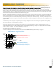
HYBRID LOGIC OVERVIEW In response to new advancement in condensing boiler design and size, many applications utilize multiple condensing boilers in addition to the non-condensing boilers. That triggered Laars's design of the M4-LHS. It is intended to manage the two groups of When Hybrid is selected as the Boiler Type, the M4-LHS will select the lead group based on the Target temperature switching set point. See "Switch Set Point" on page 20.
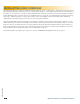
Modulating Logic Overview The Modulation PID logic is capable of controlling multiple modulating current or voltage boilers. When heat is required, the control PID activates the lead boiler and starts its purge. See "Purge Delay" on page 31. This is followed by the initiation of its modulation at the Ignition %. See "Ignition %" on page 40. When additional heat is needed, the control starts to increase the lead boiler modulation until the Modulation Start % has been reached.
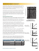
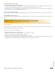
Outdoor Reset Concept 1:2 1:1.5 1:1.25 210 200 1:1 190 180 1.25:1 170 1.5:1 160 150 2:1 140 3:1 4:1 130 120 Each building has different heat loss characteristics. A very well insulated building will not lose much heat to the outside air, and may need a Reset Ratio of 2.00 (OD):1.00 (SYS) (Outdoor:Water). This means the outdoor temperature would have to drop 2° to increase the water temperature 1 degree.
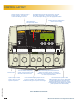
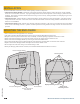
Control Layout Program Switch to restrict access to function changes. This switch is covered with Wiring Enclosure. The digital display shows the system status, set point, lead stage , and status of each stage. To view and adjust settings, press the appropriate buttons. Buttons function is presented on Bottom Row of display. LED indicates the associated relay status.
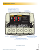
Extension Layout Extension Selection Switch to determine Stage letters and LED colors. Ext-A Stages E - J and all LEDs are Green Ext-B Stages K - P and all LEDs are Red This switch is covered with the Wiring Enclosure. LED indicates the associated relay status.
Features Laars designed the M4-LHS with Hydronic building heating, using both condensing and non-condensing boilers, as the primary purpose. In addition, the M4-LHS is capable of controlling modulating and staging boilers. With this in mind, many of the M4-LHS features can be utilized to ease, enhance, and improve your system performance. Condensing and Non-Condensing Boilers Can be Modulating or Multi-Stage. The M4-LHS can operate both modulating and staging boilers.
Setback or Day/Night Scheduling Two Setback modes are available for the M4-LHS: • The Day/Night Scheduling provides an adjustable time-based schedule for the Setback (only available when Shutdown or Tstat is selected as the Setback/Shutdown Startup option). See "Shutdown/Tstat/Setback Mode" on page 24. • The Setback mode uses an external signal to switch the operation of the M4-LHS in and out of setback mode (only available when Setback is selected as the Setback/Shutdown Startup option).
Installation Each of the M4-LHS or Extension consists of three primary enclosure components. • The Enclosure Display Module: contains the control electronic board, display, buttons, LEDs, and electric wiring terminals. It has two screws to hold it to the base. A program configuration switch, used to adjust the control settings, is placed above the terminals. This switch is enclosed with the enclosure wiring cover for security. Wiring terminals are of the plug-in type to ease installation and removal.
Install the Sensors Immersion Heating System Sensor System Sensor Installation • Only use the System sensor (CA002500 or equivalent) provided with the unit. • The sensor wires can be extended up to 500' using a shielded 2-conductor cable (Belden #8760 or equivalent). Do not ground the shield at the sensor but at the panel using one of the terminals marked with an “O”. • Do not run sensor wires in conduit with line voltage wiring. • Install a 3/8"ID 1/2"NPT immersion well.
ENCLOSED ENERGY MANAGEMENT EQUIPMENT 99RA Wiring • All wiring must enter the enclosure through the bottom knockouts. • Class 1 voltage wiring must utilize a different knockout and conduit from any Class 2 voltage wiring. M4-LHS OUTPUT RATINGS: 120VAC, 6A RESISTIVE ENCLOSED ENERGY MANAGEMENT EQUIPMENT 3 4 5 6 7 1 2 A 1A PILOT DUTY, 15A TOTAL (Terminals 1, 2) FOR ALL CIRCUITS • Bring the 120VAC 60Hz power wires through the bottom left knockout of the enclosure.
M4-LHS HYBRID CONTROL SYSTEM OUTPUT RATINGS: 120VAC, 6A RESISTIVE 1A PILOT DUTY, 15A TOTAL • When the Shutdown input is enabled by closing the dry contact, or when the Tstat Ainput is disabled by opening the FOR ALL CIRCUITS INPUT RATINGS: dry-contact, all active modulating boilers will immediately modulate down to lowBfor the Soft-Off period, then turn 115VAC 60Hz , 30VA MAX off. All staging boilers will turn off immediately. USE COPPER WIRE, C and then it will turn off. CLASS 1 until WIRE ONLY.
CAUTION: RISK O More than one disco to de-energize the eq MANAGEMENT EQUIPMENT 99RA M Wiring the Boilers OUTPUT RATINGS: SYS PWR 120VAC, 6A RESISTIVE PILOT DUTY, 15A TOTAL • When wiring Condensing and Non-Condensing boilers make sure that the Condensing boilers use the first1A L N FOR ALL CIRCUITS stages and the Non-Condensing boilers use the following stages.
ENCLOSED ENERGY MANAGEMENT EQUIPMENT CAUTION: RISK OF ELECTRIC SHOCK More than one disconnect switch may be required to de-energize the equipment before servicing. 99RA Connecting to the Extensions and 4-20mA EMS Interface PWR Alert L N SYS A B PROGRAM A D C RUN B C D CUR / VLT CUR / VLT CUR / VLT CUR / VLT GND - To set the Extension to a specific letter, remove the wiring cover and switch the Ext A/Ext B to the 3 4 5 6 7 8 9 10 11 12 1 2 desired letter.
Connecting to BACnet Interface Module • The M4-LHS can communicate to BACnet MSTP networks when used the X-BAC BACnet Interface Module (CA009100). The module must be purchased separately. • The BACnet Interface Module comes with an RJ45 cable. • Both the M4-LHS and the BACnet Interface Module are equipped with a RJ45 socket (RS485) to connect to communicate to each other. • The Interface BACnet Module must be wired to the BACnet MSTP network using the RS485 terminals A, GND, and B.
HYBRID Startup Menu Page 20 -EMS 20ma SETPOINT220 oF ] ▲ ▼ SAVE [ BACK 4ma SETPOINT 70 oF ▲ ▼ - ] SAVE DELAY 0.
Modulating Startup Menu -- ARE YOU SURE? -No Yes BACK ▲ ▼ SAVE -------- SETTINGS ---Season Winter System Target 140oF BACK ▲ ▼ SELECT [ BACK ▲ ] SAVE -EMS 20ma ▼ SETPOINT- 220 oF ▲ ▼ ] SAVE - EMS INPUT MODE Disable Enable BACK ▲ ▼ SAVE ▲ TYPE ▼ --- SAVE To be able to change the M4-LHS settings the Program/Run Switch must be set to Program. The switch is located under the Enclosure Wiring Cover for security.
99RA Startup Settings CAUTION: RISK OF ELECTRIC SHOCK More than one disconnect switch may be required to de-energize the equipment before servicing. Program Change Switch Setting To be able to change the M4-LHS settings the Program/Run Switch must be set to Program. C B The switch is located under the Enclosure Wiring CoverPWR for security.SYS A Startup Sequence PROGRAM D 1 2 GND 3 4 5 6 7 8 9 10 11 12 Boiler Type Modulation, Hybrid Default: Modulation Button: MENU//....
EMS 4mA and 20mA Set Points 4mA: can be set from 50°F/ 10°C to 200°F/93°C Default: 70°F/ 21°C 20mA: can be set from 70°F/ 21°C to 220°F/104°C Default: 220°F/ 104°C Button: MENU//..../Sensor Type / EMS Input Mode/EMS 4mA Set Point • With the use of the 4-20mA EMS Interface, the M4-LHS will be able to receive a 4-20mA signal as a set point from a BMS or an EMS system as the target set point.
Heavy Load Sequence 2nd Group Yes, No Default: No Button: MENU//..../Switch Delay/Heavy Load Seq#2 Group • This option makes the second group of boilers act as a backup in heavy load conditions. Thus, allowing them to start after all lead group boilers have run at their maximum capacity. • If the system was designed to operate both groups of boilers in heavy load conditions, then select Yes. • Selecting No will only allow the lead group to operate.
HYBRID Modulating Boiler Settings Modulating Output Type 4-20mA, 0-10V, 1-10V (Custom) Outputs Default: 1-10v Custom Button: MENU//..../Condensing Boiler Number/Output A Type • If either of the Condensing or Non-Condensing Boiler groups was set to Modulating as the Boiler Type, the M4-LHS will offer the capability of controlling a variety of modulating signals. Each boiler can be configured to have a different modulating signal.
Modulating Boiler Settings Adjustable from 1 to 15 Button: MENU//Boiler Type/.../Boiler Number • Select the number of modulating boilers. Default: 1 Modulating Output Type 4-20mA, 0-10V, 1-10V (Custom) Outputs Default: 1-10v Custom Button: MENU//..../Boiler Number/Output A Type • The M4-LHS will offer the capability of controlling a variety of modulating signals. Each boiler can be configured to have a different modulating signal.
Startup Settings (Continued) Prove/Indirect Domestic Hot Water (DHW) Priority Prove, DHW Priority, DHW No Priority, No Priority (Summer) Default: Prove Button: MENU//..../Prove-DHW Sharing • This setting determines the functionality of input terminals 29 and 30. • When Prove is selected, the M4-LHS will not start any boiler unless the Prove terminals are shorted/closed. However, it will allow the System relay to operate normally. • There are three DHW Priority options.
Boost Mode (Not Available in Setback Mode) 30 Minutes, Disabled Default: Disable Button: MENU//..../Boost Mode • The morning Boost is designed to return the building to comfortable ambient temperatures after the cooler Night (Setback) period. The control will accomplish this by running elevated water temperatures (will add Setback setting to calculated water temperature) for 30 minutes before the start of the Day schedule setting.
BACnet MSTP Communication Menu -------- SETTINGS ---Season Winter System Target 140oF BACK ▲ ▼ SELECT ---[ BACK BACNET ID 477000 ▲ ▼ ---] SAVE -- ARE YOU SURE? -No Yes BACK ▲ ▼ SAVE ----MS/TP [ BACK - BACNET BAUDRATE 9600 19200 38400 BACK ▲ ▼ SAVE ADDRESS---- 64 ▲ --- BACNET MODE --Disable Enable BACK ▲ ▼ SAVE ▼ ] SAVE When using the M4-LHS in a BACnet MS/TP network, the use of BACnet Interface Module is required.
99RA Operating Settings CAUTION: RISK OF ELECTRIC SHOCK More than one disconnect switch may be required to de-energize the equipment before servicing. Program Change Switch Setting PROGRAM To be able to change the M4-LHS settings, the Program/Run Switch must be set to Program. D C B The switch is located under the Enclosure Wiring CoverPWR for security.SYS A A Winter, Summer Default: Winter Button: MENU/Season • The M4-LHS will turn all boiler relays off when it is in Summer setting.
HYBRID Operating Menu 55oF OD= SYS=143oF <> 67% B 22% STAGE ◄ ------[ BACK --- -- SETBACK 10 oF ▲ PURGE [ BACK ► ------] SAVE ▼ DELAY 1.0 min ▲ ▼ SYSTEM [ BACK MENU --] SAVE RUN-ON 10 min ▲ ▼ -- ----- SEASON Winter Summer -------- SETTINGS ---Season Winter o System Target 140 F BACK ▲ ▼ BACK SELECT Alert To be able to change the M4-LHS settings the Program/Run Switch must be set to Program.
Modulating Operating Menu SYS=143oF 67% B 22% STAGE ◄ ► MENU ----- SEASON Winter Summer ▲ BACK [ BACK --- ▲ ▼ min ▲ ▼ ▼ STANDBY [ BACK 10 LAST [ ] BACK ] SAVE ----- SET ▲ ▼ STAGE -- ] SAVE HOLD 5 oF ▲ ▼ To be able to change the M4-LHS settings the Program/Run Switch must be set to Program. The switch is located under the Enclosure Wiring Cover for security. The Enclosure Wiring Cover can be secured using a lock.
Offset ------- OFFSET +0 oF [ BACK ▲ 170 150 R o ati tR e es 0 +1 Hybrid Default: 70ºF/ 21ºC Modulation Default: 120ºF/ 49ºC Button: MENU/System Target/Offset/Outdoor Cutoff/Minimum Water Temp • The Minimum Water Temperature must be set to the boiler manufacturer’s specification. The M4-LHS will calculate the Set Point based on the Outdoor Temperature (OD), the Reset Ratio, and the Offset value.
System Settings Button: MENU/ Settings 1 and Settings 2 menus provide access to adjusting and fine-tuning the system for RATINGS: enhanced comfort and better fuel savings. The M4-LHS behavesOUTPUT differently based on the 120VAC, 6A RESISTIVE 1A PILOT DUTY, 15A TOTAL selected modes. See "Startup Settings" on page 19. FOR ALL CIRCUITS INPUT RATINGS: Alert 115VAC 60Hz , 30VA MAX USE COPPER WIRE, CLASS 1 WIRE ONLY. M4-LHS H ----- SETTINGS 1 ---o Setback SYSTEM 0 F Purge Delay 1.
• The System Run-On time should be set based on the size and type of the boilers and pumps used. In general, when setting the System Run-On consult the boiler and pump manufacturers for the best setting. • When the System relay is in the Run-On period, the Message Display Line will indicate that status and the remaining time.
Modulating Boiler Operating Settings Gain Adjustable from -10 to +10 Default: 0 Button: MENU////Gain • The Gain adjusts the aggressiveness of the modulating PID logic. It controls how much modulation is changed when the system temperature is different from the Set Point. • A Gain of 0 is a good starting point for all systems.
Staging Boiler Operating Settings Reaction Time Adjustable from 1 to 10 minutes Default: 2 minutes Button: MENU////Reaction Time • It is the amount of time it takes a single stage to affect the system. • After the control turns on a stage trying to meet the set point, it will not turn on another stage until the Reaction Time has elapsed. • To determine the optimum time, start with a hot system.
M4-LHS Installation and Operation Manual WARNING The temperature limits set on the boilers must be higher than the M4-LHS Max Water Temp. Read the left section for details that will prevent erratic system operation. 35 HT# 059295-00 A Avoiding Conflicting Boiler Limits The temperature limits set on the boilers MUST be set considerably higher than the M4-LHS's Set Point for the reasons detailed below. • The M4-LHS sensor is located in a common header some distance from the boilers.
Day - Night Schedule (Available when "Shutdown or Tstat" is selected from the Shutdown/Tstat/ Setback Startup menu option only) Button: MENU///Day/Night Schedule • The M4-LHS has two levels of heat. The Day (Normal) level is used when a building is occupied and people are active. • The Night (Setback) level is used when a building is not occupied, or when people are sleeping. This setting reduces the calculated temperature by the Setback setting. See "Setback" on page 31.
Output Modulation Trim (Available for modulating boilers only) Adjustable from -1.0 to +1.0 Default: 0.0 Button: MENU//Output Trim • Each of the modulating stages controlled has a separate Output Trim setting. • Output Trim acts as an adjustment to a stage output percent to match the burner motor. • After adjusting the Output Trim, test the operation to make sure the results match your expectation. -- STAGE A TRIM --Output Trim +0.
Boiler Status The M4-LHS boiler status gives immediate access to each boiler stages or modulation. • --- Boiler is off due to no call for heat. • <> A is the lead boiler in the lead Hybrid group. See "Lead Stages" on page 32. • C is the lead boiler in the lag Hybrid group or the lead boiler in Modulating Boiler Type. See "Lead Stages" on page 32. • C/E Extension panel is NOT communicating back to the M4-LHS. See "Connecting to the Extensions and 4-20mA EMS Interface" on page 15.
OD= 55oF SYS=143oF <> 67% B 20% STAGE ◄ Staging ▲ STAGE Auto Standby Manual Off On BACK ▲ ▼ A MENU - Modulation STAGE A SETTINGS Mode Auto BACK ► SELECT MODE STAGE A IGNITION POINT 1% [ STAGE A SETTINGS Mode Auto Ignition % 1% Mod Start % 80% Copy Settings BACK ▲ ▼ SELECT BACK ▲ ] ▼ SAVE STAGE A MODULATION START 75% [ BACK ▼ - ▲ ] ▼ SAVE SAVE Button: STAGE/ Modulating Boiler Stage Menu The Stage menu provides adjustment
Auto The M4-LHS will control the boiler’s operation to maintain the desired Set Point. Only boilers set to Auto can be Lead boilers. Standby Standby boilers can only be activated when all boilers in Auto have been at 100% modulation or at High fire for the full Standby Time. Standby is generally used when you want a specific boiler to be available in extreme load conditions. Note that a Standby boiler Cannot be a Lead boiler. Manual Available For modulating boilers only.
Troubleshooting When the display shows sensor SHORT, remove the wires from the sensor terminals. The display should change to read OPEN. In this case, replace the sensor. Otherwise, if the display does not show OPEN, the M4-LHS may be damaged. Display shows an Incorrect Temperature Remove the wires from the sensor terminals. The display should change to read OPEN. If it does not, the M4-LHS may be damaged. Take an ohm reading across the detached sensor wires.
Too Little Heat • Reset Ratio and Offset - If reduced heat occurs only in certain weather conditions, adjust the Reset Ratio and Offset (See "Outdoor Reset Concept" on page 5). If reduced heat occurs year round, increase the Offset. • Setback and Day/Night Schedule - If reduced heat occurs only during specific hours, check the Day/Night Schedule and the Setback values. Then, reduce the Setback setting. See "Setback" on page 31.
Specifications Voltage Input: . . . . . . . . . . . . . . . . . . . . . . . . . . . . . . . . . . . . . . . . . . . . . . . . . . . . 120 VAC 60 Hz Power Consumption: . . . . . . . . . . . . . . . . . . . . . . . . . . . . . . . . . . . . . . . . . . . . . . . . . . 12 VA Max Operating Temperature: . . . . . . . . . . . . . . . . . . . . . . . . . . . . . . . . . . . .
Read Only Read Only Read Only Object Value BINARY-VALUE BINARY-VALUE 400 500 600 700 800 900 1000 1100 1200 1300 1400 1500 1600 1700 1800 1900 2000 2100 2200 2300 2400 2500 2600 2700 2800 - Max Stages Control Status Season Reset Ratio Offset Outdoor Cutoff Min Water Temp Max Water Temp Setback Purge Delay System Runon Rotation Time Standby Time Last Stage Hold Con Lead Stage Non-Con Lead Stage Reaction Time Min Run Time Gain Lag Delay Soft off Set Time Day
M4-LHS Installation and Operation Manual Read Only Read Only Read Only Object Value BINARY-VALUE BINARY-VALUE 400 500 600 700 800 900 1000 1100 1200 1300 1400 1500 1600 1700 1800 1900 2000 2100 2200 2300 2400 - Max Stages Control Status Season Reset Ratio Offset Outdoor Cutoff Min Water Temp Max Water Temp Setback Purge Delay System Runon Rotation Time Standby Time Last Stage Hold Gain Lag Delay Soft off Set Time Day Schedule Night Schedule System Relay Output R
Read Only Read Only Read Only Object Value BINARY-VALUE BINARY-VALUE 400 500 600 700 800 900 1000 1100 1200 1300 1400 1500 1600 1700 1800 1900 2000 2100 - Max Stages Control Status Season Setpoint Outdoor Cutoff Setback Purge Delay System Runon Rotation Time Standby Time Last Stage Hold Gain Lag Delay Soft off Set Time Day Schedule Night Schedule System Relay Output Relays Read Only Read/Write Read/Write Read/Write Read/Write Read/Write Read/Write Read/Write
BACnet PICS Statement Product Model Number Protocol Revision Software Version Firmware Version M4-LHS BACnet Control Varies 1.5 2.0 2.0 Vendor Vendor ID Address and Phone Laars Product Description M4-LHS control for hot water heating applications. (see http://www.Laars.
PIPING AND WIRING DIAGRAMS HYBRID PIPING DIAGRAM Outdoor Sensor M4-LHS HYBRID CONTROL SYSTEM Two Modulating Condensing Boilers and Two On/Off NonCondensing Boilers A B C D PROGRAM PWR SYS A B C D L N 1 2 A DO NOT APPLY ANY VOLTAGE TO INPUT TERMINALS RUN C B D CUR / VLT CUR / VLT CUR / VLT CUR / VLT GND 3 4 5 6 7 8 9 10 11 12 - mA + VLT + GND - mA + VLT + GND - mA + VLT + GND - mA + VLT + 13 14 15 16 17 18 19 20 21 22 23 24 OUTDOOR TEMP T O SYSTEM TEMP T O P
HYBriD WiriNg DiagraM M4-LHS Two 4-20ma Modulating Condensing Boilers and Two On/Off NonCondensing Boilers HYBRID CONTROL SYSTEM OUTPUT RATINGS: 120VAC, 6A RESISTIVE 1A PILOT DUTY, 15A TOTAL FOR ALL CIRCUITS A INPUT RATINGS: 115VAC 60Hz , 30VA MAX B USE COPPER WIRE, CLASS 1 WIRE ONLY. C D ENCLOSED ENERGY MANAGEMENT EQUIPMENT CauTiON: RISK OF ELECTRIC SHOCK More than one disconnect switch may be required to de-energize the equipment before servicing.
MODULATING PIPING DIAGRAM Outdoor Sensor Four Modulating Boilers M4-LHS STARTUP SETTINGS Boiler Type = Modulation Boiler Number = 4 HYBRID CONTROL SYSTEM A B C D PROGRAM PWR SYS A C B D L N 1 2 A DO NOT APPLY ANY VOLTAGE TO INPUT TERMINALS RUN D C B CUR / VLT CUR / VLT CUR / VLT CUR / VLT GND 3 4 5 6 7 8 9 10 11 12 - mA + VLT + GND - mA + VLT + GND - mA + VLT + GND - mA + VLT + 13 14 15 16 17 18 19 20 21 22 23 24 OUTDOOR TEMP T O SYSTEM TEMP T O PROVE SHUTD
Piping and Wiring Diagrams Hybrid Piping Diagram Outdoor Sensor M4-LHS HYBRID CONTROL SYSTEM Two Modulating Condensing Boilers and Two On/Off NonCondensing Boilers A B C D PROGRAM PWR SYS A C B D L N 1 2 A DO NOT APPLY ANY VOLTAGE TO INPUT TERMINALS RUN C B D CUR / VLT CUR / VLT CUR / VLT CUR / VLT GND 3 4 5 6 7 8 9 10 11 12 - mA + VLT + GND - mA + VLT + GND - mA + VLT + GND - mA + VLT + 13 14 15 16 17 18 19 20 21 22 23 24 OUTDOOR TEMP T O SYSTEM TEMP T O P
Hybrid Wiring Diagram M4-LHS Two 4-20mA Modulating Condensing Boilers and Two On/Off NonCondensing Boilers HYBRID CONTROL SYSTEM OUTPUT RATINGS: 120VAC, 6A RESISTIVE 1A PILOT DUTY, 15A TOTAL FOR ALL CIRCUITS A INPUT RATINGS: 115VAC 60Hz , 30VA MAX B USE COPPER WIRE, CLASS 1 WIRE ONLY. C D ENCLOSED ENERGY MANAGEMENT EQUIPMENT CAUTION: RISK OF ELECTRIC SHOCK More than one disconnect switch may be required to de-energize the equipment before servicing.
Modulating Piping Diagram Outdoor Sensor Four Modulating Boilers M4-LHS Startup Settings Boiler Type = Modulation Boiler Number = 4 HYBRID CONTROL SYSTEM A B C D PROGRAM PWR SYS A C B D L N 1 2 A DO NOT APPLY ANY VOLTAGE TO INPUT TERMINALS RUN C B D CUR / VLT CUR / VLT CUR / VLT CUR / VLT GND 3 4 5 6 7 8 9 10 11 12 - mA + VLT + GND - mA + VLT + GND - mA + VLT + GND - mA + VLT + 13 14 15 16 17 18 19 20 21 22 23 24 OUTDOOR TEMP T O SYSTEM TEMP T O PROVE SHUTD
Modulating Wiring Diagram M4-LHS Four 4-20mA Modulating Boilers HYBRID CONTROL SYSTEM OUTPUT RATINGS: 120VAC, 6A RESISTIVE 1A PILOT DUTY, 15A TOTAL FOR ALL CIRCUITS A INPUT RATINGS: 115VAC 60Hz , 30VA MAX B USE COPPER WIRE, CLASS 1 WIRE ONLY. C D CAUTION: RISK OF ELECTRIC SHOCK More than one disconnect switch may be required to de-energize the equipment before servicing.
HTC# 059295-00 A 20 Industrial Way, Rochester, NH 03867 • 603.335.6300 • FAX 603.335.3355 1355 Kuehner Drive, Simi Valley, CA 93063 • 800.900.9267 • FAX 800.559.1583 (Sales, Service) 1869 Sismet Road, Mississauga, Ontario, Canada L4W 1W8 • 905.238.0100 • FAX 905.366.0130 www.laars.com Litho in U.S.