Installation and Operation Instructions Document 1276C Installation and Operation Instructions for MAGNATHERM Modulating Boiler Water Heater Model MGH2000 Model MGV2000 1,999 MBTU/h 1,999 MBTU/h Model MGH2500 Model MGV2500 2,499 MBTU/h 2,499 MBTU/h Model MGH3000 Model MGV3000 3,000 MBTU/h 3,000 MBTU/h Model MGH3500 Model MGV3500 3,500 MBTU/h 3,500 MBTU/h Model MGH4000 Model MGV4000 4,000 MBTU/h ® 4,000 MBTU/h FOR YOUR SAFETY: This product must be installed and serviced by a profess
LAARS Heating Systems Table of Contents Section 1 - GENERAL INFORMATION 1.1 1.2 1.3 1.4 1.5 1.6 1.7 Introduction.......................................................1 Safety Notes...................................................... 1 Model Nomenclature / Identification................ 2 Warranty............................................................2 Unit Overviews ( all sizes )............................3-5 Dimensions........................................................ 6 Unpacking..........
MagnaTherm Boilers and Water Heaters Section 9 – NAVIGATING THE TOUCH SCREEN Section 11 – MAINTENANCE 9.1 9.2 9.3 9.4 9.5 9.6 11.1 11.2 11.2.1 11.2.2 11.2.3 11.2.4 11.2.5 11.2.6 11.2.7 11.2.8 The Touch Screen ...........................................40 Using the Touch Screen...................................40 Verification Process for Safety-Related Parameters.......................................................42 While Operating - Checking Individual Parameters...........................
LAARS Heating Systems
MagnaTherm Boilers and Water Heaters Page 1 Section 1 GENERAL INFORMATION 1.1 Introduction This manual includes information which will help you to install, operate, and maintain the MagnaTherm 2000, 2500, 3000, 3500 and 4000 systems. Please read this manual completely before proceeding with the installation. If you have any questions regarding this equipment, please consult the LAARS Heating Systems factory, or a local factory representative. Many operating problems are caused by improper installation.
Page 2 LAARS Heating Systems 2 M G SERIES M G 3 4 USAGE H - HYDRONIC V - VOLUME WATER 1.
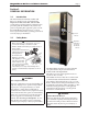
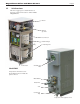
MagnaTherm Boilers and Water Heaters 1.5 Page 3 Unit Overviews The next 3 pages give a visual reference to the basic component locations of the LAARS MagnaTherm. Blower Manual gas valve Touch Screen Heat Exchanger Condensing Unit Power Pack Air Intake and Filter Model 2000 Perspective from front left corner. Shown with front doors and left side panels removed Water Outlet Water Inlet Vent Condensate Trap Perspective from opposite corner.
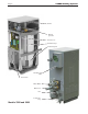
Page 4 LAARS Heating Systems Blower Manual gas valve Touch Screen Heat Exchanger Condensing Unit Air Intake and Filter Power Pack Water Outlet Water Inlet Vent Condensate Trap Models 2500 and 3000
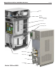
MagnaTherm Boilers and Water Heaters Page 5 Blower Manual gas valve (hidden behind main gas valve) Touch Screen Heat Exchanger Condensing Unit Air Intake and Filter Water Outlet Power Pack Water Inlet Vent Condensate Trap Models 3500 and 4000
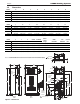
Page 6 1.6 LAARS Heating Systems Dimensions Model A B C D E F G H J Inches (cm ) G K Inches (cm ) 2000 29.3 (75 ) 79 (201 ) 38 (96 ) 57.5 (147 ) 49.8 (126 ) 4.8 (12 ) 60.8 (154 ) 2.6 (7 ) 8.4 (21 ) 67.4 (1 2500 30.8 (78) 87 (221 ) 41.5 (105 ) 60.5 (154 ) 60.8 (154 ) 6.5 (16 ) 71 (180 ) 4 (10) 9.8 (25 ) 76.4 (1 3000 30.8 (78) 87 (221 ) 41.5 (105 ) 60.5 (154 ) 60.8 (154 ) 6.5 (16 ) 71 (180 ) 4 (10) 8.9 (23 ) 76.8 (1 3500 34.
Page 7 MagnaTherm Boilers and Water Heaters 1.7 Unpacking The MagnaTherm is shipped in a single crate. Remove all packing and tie-down materials. Section 2 LOCATING THE APPLIANCE Note - When located on the same wall, the MagnaTherm combustion air intake terminal must be installed a minimum of 12” (30cm) below the exhaust terminal. There must also be a minimum horizontal distance from intake to the exhaust terminal of 84” (213cm) See Figure 4 APPLIANCE SUGGESTED SERVICE ACCESS CLEARANCE SURFACE 2.
Page 8 LAARS Heating Systems Section 3 VENTING AND COMBUSTION AIR 3.1 Combustion Air MagnaTherm boilers and water heaters must have provisions for combustion and ventilation air in accordance with the applicable requirements for Combustion Air Supply and Ventilation in the National Fuel Gas Code, ANSI Z223 1; or in Canada, the Natural Gas and Propane Installation Code, CSA B149.1. All applicable provisions of local building codes must also be adhered to.
Page 9 MagnaTherm Boilers and Water Heaters 3.2 with the outdoors and shall have a minimum free area of 1 square inch per 3000 Btu/hr (734 square mm/kW) of the total input rating of all equipment located in the enclosure. This opening must not be less than the sum of the areas of all vent connectors in the confined space. Other methods of introducing combustion and ventilation air are acceptable, providing they conform to the requirements in the applicable codes listed above.
Page 10 LAARS Heating Systems If the system temperatures are unknown at the time of installation, class IIC or higher venting material is recommended. The MagnaTherm is a Category IV appliance and may be installed with the standards listed on Table 6. The unit’s vent can terminate through the roof, or through an outside wall. This will allow the condensate to run back to the MagnaTherm to drain. Route the vent pipe to the heater as directly as possible. Seal all joints.
MagnaTherm Boilers and Water Heaters Page 11 Category IV appliances. Per the requirements of CAN/CSA-B149.1, only BH vent systems can be connected to these units and such vent systems, either ULC S636 certified stainless steel or other ULC S636 certified BH vent (eg. plastics) must be installed per the vent manufacturer’s certified installation instructions.
Page 12 LAARS Heating Systems U.S. Installations (see note 1) Canadian Installations (see note 2) A= Clearance above grade, veranda, porch, deck, or balcony 12 inches (30 cm) See note 6 12 inches (30 cm) See note 6 B= Clearance to window or door that may be opened Direct vent only: 12 inches (30 cm); Other than Direct vent: 4 ft (1.
Page 13 MagnaTherm Boilers and Water Heaters 84 IMPORTANT: All terminals must be placed so that they remain at least 12” above the expected snow line. Local codes may have more specific requirements, and must be consulted. Refer to the NFPA54 National Fuel Gas Code and your local codes for all required clearances for venting. Figure 5. Multiple Side-Wall Terminals, Air and Vent 5. 6. 7. cannot enter the building through doors, windows, gravity inlets or other openings.
Page 14 LAARS Heating Systems 3.3.4 Vertical Combustion Air Terminal When combustion air is taken from the roof, a fieldsupplied rain cap or an elbow arrangement must be used to prevent entry of rain water. The opening on the end of the terminal must be at least 12” (30 cm) above the point at which it penetrates the roof, and high enough above the roof line to prevent blockage from snow. When the vent terminates on the roof, the combustion air must terminate at least 12” (30 cm) below the vent terminal.
MagnaTherm Boilers and Water Heaters When an existing boiler is removed from a common venting system, the common venting system is likely to be too large for proper venting of the appliances remaining connected to it. At the time of removal of an existing boiler, the following steps shall be followed with each appliance remaining connected to the common venting system placed in operation, while the other appliances remaining connected to the common venting system are not in operation. 1.
Page (Place16in section 3.5) LAARS Heating Systems Model 2000 Model 2500 Model 3000 Model 3500 Model 4000 Air intake screen for unit placed outdoors CA011901 CA011901 CA011902 CA0011903 CA0011903 Vent terminal for unit placed outdoors CA011801 CA011801 CA011802 CA011803 CA011803 Table for Units UnitsPlaced PlacedOutdoors Outdoors Table7.3** -Air Air&&Vent Ventaccessories Accessories for 3.
MagnaTherm Boilers and Water Heaters The following are gas line sizing examples from the National Fuel Gas Code. Size your gas lines properly, based on your installation, and all applicable codes. SCH 40 METAL PIPE CAPACITY FOR 0.60 SPECIFIC GRAVITY NATURAL GAS Natural NOMINAL PIPE SIZE @ 0.30” W.C.Gas PRESSURE DROP Pipe Size (in.) Nominal: 2 2½ 3 4 5 Actual ID: 2.067 2.469 3.068 4.026 5.
3500 4000 30.8 34.5 78 88 87 97 221 246 41.5 52.0 Page 18 105 132 F ead Loss Feet 13.6 13.6 18.9 18.6 22.5 3 4 2 2.5 LAARS Heating Systems Input Rate Size Bo Output Rate (NPT) MBH kW WATER(NPT) FLOW REQUIREMENTS Boiler Water Flow Requirements 2.5 1.5 2000 1999 586 2.5 1.5 2500 2499 732 5.1 MagnaTherm Boiler Flow and Head Requirements Temperature Rise in °F 3 2 3000 3000 879 25°F 30°F 35°F 3500 3 2 3500 40°F1025 Size Flow Head Loss* Flow Head Loss* Flow Head Loss* 4000 Flow Head 4 2.
Page 19 MagnaTherm Boilers and Water Heaters Section 6 WATER CONNECTIONS MGH BOILERS 6.1 MGH System Piping: Hot Supply Connections Note -This appliance must be installed in a closed pressure system with a minimum of 12 psi (82.7 kPa) static pressure at the boiler. The hot water piping should be supported by suitable hangers or floor stands. Do not support the piping with this appliance. The hangers used should allow for expansion and contraction of pipe.
Page 20 LAARS Heating Systems Different glycol products may provide varying degrees of protection. Glycol products must be maintained properly in a heating system, or they may become ineffective. Consult the glycol specifications, or the glycol manufacturer, for information about specific products, maintenance of solutions, and set up according to your particular conditions. The following manufacturers offer glycols, inhibitors, and anti foamants that are suitable for use in the MagnaTherm.
Page 21 MagnaTherm Boilers and Water Heaters Low temp. radiant zone Space heating zone circuits Space heating zone circuit Air vent System pump Water feed controls 4 pipe dia. max. 4 pipe dia. max. 4 pipe dia. max. Note This drawing is a schematic representation of a piping style, and is not intended to be used as a working installation drawing. Local code requirements must be met. Figure 7. Hydronic Piping — Single Boiler, Multiple Temperature Zones Zoning with circulators 4 pipe dia. max.
Page 22 LAARS Heating Systems Note This drawing is a schematic representation of a piping style, and is not intended to be used as a working installation drawing. Local code requirements must be met. Low temp. radiant zone Low temp. radiant zone Air vent Water feed controls Expansion tank 4 pipe dia. max. Anti-scald mixing valve Indirect DHW tank Domestic hot water out Cold water Figure 8.
Page 23 MagnaTherm Boilers and Water Heaters Note This drawing is a schematic representation of a piping style, and is not intended to be used as a working installation drawing. Local code requirements must be met. Space heating zone circuits Low temp. radiant zone Space heating zone circuit Air vent Water feed controls 4 pipe dia. max. 4 pipe dia. max. Expansion tank 4 pipe dia. max. Common piping must be sized for the combined water flow of all of the boilers. Figure 9.
Page 24 LAARS Heating Systems Space heating zone circuits High temp. space heating zone circuit Space heating zone circuit Air vent Water feed controls 4 pipe dia. max. 4 pipe dia. max. Expansion tank 4 pipe dia. max. Common piping must be sized for the combined water flow of all the boilers. Note This drawing is a schematic representation of a piping style, and is not intended to be used as a working installation drawing. Local code requirements must be met.
Page 25 MagnaTherm Boilers and Water Heaters Section 7 WATER CONNECTIONS MGV UNITS 7.1 MGV Water Quality MGV water heaters must be installed in water conditions of 15 gpg hardness or less, with a pH range of 6.5 to 9.5 pH. Values outside of this range may reduce the life expectancy of the product.
Page 26 LAARS Heating Systems event of pressure relief. Install a diaphragm-type expansion tank, flow check, and shutoff valves where needed or as required by code. The piping should be installed so that each pump supplies flow only to the heater to which it is attached. 7.5 MGV Freeze Protection If installing outdoors in a location that may experience freezing temperatures, precautions must be taken to prevent water in the heat exchanger and condensate inside and outside of the boiler from freezing.
Page 27 MagnaTherm Boilers and Water Heaters Building return NOTES: 1. Locate the MGV DHW sensor or remote aquastat well 2 in lower 1/3 of tank. Cold water 2. Back flow preventer may be supply required - check local codes. 3. Thermal expansion tank may be 3 required - check local codes. Expansion 4. Caution: Pump sizing must tank be based upon water hardness at job site. 5. I f the tank does not have a tapping for the cold water supply, the supply may be run to the pipe between the tank and boiler inlet.
Page 28 LAARS Heating Systems Section 8 ELECTRICAL CONNECTIONS 8.1 Installation Warnings WARNING The appliance must be electrically grounded in accordance with the requirements of the authority having jurisdiction or, in the absence of such requirements, with the latest edition of the National Electrical Code, ANSI/NFPA 70, in the U.S. and with the latest edition of CSA C22.1 Canadian Electrical Code, Part 1, in Canada. Do not rely on the gas or water piping to ground the metal parts of the boiler.
Page 29 MagnaTherm Boilers and Water Heaters Model 2000 Voltage Nominal Current FLA 2500 / 3000 3500 / 4000 120 220 208 3ø 480 3ø 600 3ø 120 220 208 3ø 480 3ø 600 3ø 120 220 208 3ø 480 3ø 600 3ø 15.1 8.8 7.0 3.2 2.8 N/A N/A 12.5 5.0 4.0 N/A N/A 113 4.8 4.4 22.6 11.3 12.7 6.2 4.5 N/A N/A 19.4 8.7 5.9 N/A N/A 19.4 8.7 5.9 Table 13.
Page 30 LAARS Heating Systems 8.4 Control Panel Layout 8 9 1 7 7 5 2 PART NO. 5 3 6 2 CA0099 1 KM004400 2 E2339800 1 E2346100 1 KM004300 1 A0014300 1 A0014300 1 E0086800 1 30N7050 4 PARTS LIST PART NO. Figure 14. QTY DESCRIPTION ITEM NO.
MagnaTherm Boilers and Water Heaters Page 31
Page 32 8 6 7 5 LAARS Heating Systems THIS DOCUMENT AND THE INFORMATION CONTAINED HEREIN ARE PROPRIETARY TO LAARS HEATING SYSTEMS CO. AND SHALL NOT BE REPRODUCED, TRANSFERRED TO OTHER DOCUMENTS, USED OR DISCLOSED TO OTHERS FOR MANUFACTURING OR ANY OTHER PURPOSE EXCEPT AS SPECIFICALLY AUTHORIZED IN WRITING BY LAARS HEATING SYSTEMS CO. 8.
5 3 4 MagnaTherm Boilers and Water Heaters 2 Page 33 1 REVISIONS REV.
4 Figure 16.
Y G BL YELLOW GREEN BLUE R O RED ORANGE BK BR BROWN WIRE COLOR LEGEND GND L2 L1 220VAC BLACK Figure 17.
R O Y G RED YELLOW GREEN BROWN ORANGE BK BR BLACK WIRE COLOR LEGEND Figure 18.
Figure 19.
Figure 20.
Figure 21.
Page 40 LAARS Heating Systems Section 9 NAVIGATING THE TOUCH SCREEN The home screen shows a picture of the MagnaTherm controller. The color of the controller depends on the status of the MagnaTherm, as shown below. Color Status Touch Screen Blue Normal operation Open the front panel to access the Touch Screen Red Lockout Gray Standby mode (Burner switch off) Figure 22. To access the Touch Screen Gray and crossed out Communication problem 9.1 Yellow Hold state.
Page 41 MagnaTherm Boilers and Water Heaters To change some parameters, a password is required.
Page 42 Menu 4. LAARS Heating Systems Login Required The screen used to Login is similar to the Keyboard screen. It may be difficult for some operators to press the keys on this screen. In this case, use the back of a plastic pen, or a stylus, or a pencil eraser. (Do not use sharp metal tools – these may damage the plastic surface of the screen.) Each time you press a key, the system will respond with a beep. If you are entering a password, an asterisk (*) will appear for each character you enter.
Page 43 MagnaTherm Boilers and Water Heaters Menu 8. 6. Figure 24. Reset Button on Controller 4. The system will present a listing for each group of parameters that need verification See Menu 7. When the process is complete, the system will tell you to reset the control system. The Reset button is located on the front of the controller. You must press the Reset button within 30 seconds, or the verification will be cancelled. A count-down timer is shown at the bottom of the screen. 9.4 1. Menu 7.
Page 44 LAARS Heating Systems Menu 12. Status Summary Screen Menu 10. Status Summary Screen Notice the four buttons at the bottom of each Status Summary screen: • Configure – Allows an installer to change some of the setup parameters used by the system. A password may be required. • Operation – Used to adjust the setpoints, change the fan speed, turn a burner on or off, or turn the pumps on or off. • Diagnostics – Allows you to run diagnostic tests, or check the inputs and outputs used by the system.
Page 45 MagnaTherm Boilers and Water Heaters 9.6 Setting the Date and Time on the System Display The display includes an internal clock, which keeps track of the date and time. This setting is important, because log entries for Lockouts and Alerts include time listings. If the Date and Time setting for the boiler is not correct, the listings in the Lockout and Alert logs will be incorrect.
Page 46 LAARS Heating Systems 9.7 Configuration Menus The following sections give overviews of each configuration sub menu. 9.7.1 System Identification & Access Menu 18.
Page 47 MagnaTherm Boilers and Water Heaters A factory supplied Outdoor air temperature sensor is used with the Outdoor Reset and Warm Weather Shutdown features. 9.7.6 Demand Priority Configuration Wiring For single boiler operation, the outdoor sensor will be connected to TB1-21A and 22A.
Page 48 The controller in the Magnatherm energizes the appropriate pump contacts when it receives a call for heat. Once the call for heat is satisfied, the pumps will remain on for the defined pump overrun time. The Boiler, System, and DHW pump terminals are found on the Main control board TB1-15A through 20A. They are fed 120 Volts internally from the main power feed. The current rating of the contacts is 7.
MagnaTherm Boilers and Water Heaters Page 49 9.7.14 Burner Control Ignition 9.7.16 Sensor Configuration The Pilot test hold function allows the installer to set the pilot flame to the required pressures listed in Table 14, without turning on the Main valve. With a call for heat enabled the unit will start the normal sequence of operation to light the pilot only. Once pilot pressure has been properly set, the installer must disable call for heat and turn this feature “OFF”.
Page 50 LAARS Heating Systems 9.7.17 Lead Lag Slave Configuration Caution About Lead/Lag Operation - You should set the Modbus addresses before you connect the Modbus wiring. If the wiring is attached before the Modbus addresses on the controls are changed, there will be multiple controls with the same address, and the system will not work. If an installation includes two or more boilers, they may be set up for “Lead/Lag” operation.
Page 51 MagnaTherm Boilers and Water Heaters Number of boilers installed 1 2 3 4 5 6 7 8 Base load value 1 NA 65% 50% 35% 35% 35% 35% 35% Table 15. Base Load Settings • When the Run sequence is initiated, the boiler with the least amount of runtime will fire.
Page 52 LAARS Heating Systems You will be prompted to sign in. This can be done by pressing the ‘LOCK’ symbol at the top right Select ‘Configure’. type in ‘LNT’ and press OK. Then you can select Slave Enable. Select ‘Enable slave for built-in Lead Lag master’ . Then select OK In the Configuration Menu, Scroll down and select ‘Lead Lag Slave Configuration’. Then select a Modbus address (number) for that boiler.
Page 53 MagnaTherm Boilers and Water Heaters 9.7.18 Lead Lag Master Configuration Then set up the Master controller by going to the Lead Lag Master boiler and opening up the Lead Lag Master Configuration in that boilers Configuration Menu. Select Master Enable Wiring Connections for Lead/Lag Now you can make the Modbus wiring connections between the units. The controller in each boiler includes two wiring terminals for the Modbus system, labeled “MB1” and “MB2.
Outdoor Reset Config Low Water Temperature 40F - 200F Outdoor Reset Config Minimum Boiler Water Temp 40F - 180F 40F DHW Config DHW Enable Enable / Disable Enabled DHW Config Demand Switch Sensor Only STAT Terminal Auto: DHW (S6) or EnviroCOM DHW Auto: DHW (S6) or Sensor only DHW Sensor with On/Off Temperatures Auto:DHW (S6) or Sensor Only DHW Config Priority Method Boost During Priority Time Drop After Priority Time Drop After Priority Time Modulation Sensor DHW Sensor Outlet Sensor Inle
Frost Protection Config CH Frost Protection Enable Enable / Disable Enabled Frost Protection Config DHW Frost Protection Enable Enable / Disable Enabled Lead Lag Frost Protection Enable Enable / Disable 0% - 100% Enabled Pilot Test Hold On \ Off Off System Config Temperature Units Fahrenheit - F Celsius - C Fahrenheit - F System Config Anti- Short Cycle Time 0 min 0 sec - 15 min 0 sec 1 min 0 sec System Config Low Fire Cutoff Time 0 min 0 sec - 5 min 0 sec 0 min 0 sec System Config
Adv Settings-Algorithms 168 hrs 0 min 0 sec (7 days) Lead Lag Master ConfigAdv Settings-Algorithms Lead Rotation Time 0 min 0 sec - 1080 hrs 0 min 0 sec Lead Lag Master ConfigPage 56 Base Load Common 20% - 100% Config Group Parameter Name Available settings or Ranges Default Lead Lag Master ConfigAdv Settings - Outdoor Reset Enable Enable Disable Disabled Lead Lag Master ConfigAdv Settings - Outdoor Reset Maximum Outdoor Temperature 40F - 150F 65F Lead Lag Master ConfigAdv Settings - Outd
Page 57 MagnaTherm Boilers and Water Heaters 9.9 Connections to a Building Automation System MagnaTherm boilers can be controlled and monitored through the included Modbus ports. The Modbus wiring must be completed according to the diagrams shown below. If alternate communication protocols are desired, LAARS offers “gateways” to allow BACnet, LON, and other communications protocols. For additional information on setting up Modbus and other communication protocols, contact the factory.
Page 58 LAARS Heating Systems 9.10 Vari-Prime Vari-Prime is a variable pump control that is standard equipment on all MGH boilers. Pump speed is controlled to maintain a user-chosen temperature rise between the inlet and outlet of the MagnaTherm. General PCB Operation 1.
Page 59 MagnaTherm Boilers and Water Heaters 9.11 – Combustion Setup Procedure In this section, we will explain how to set up the gas valve so the boiler will run efficiently at both the High Fire and Low Fire conditions. Required tools: Screwdrivers, Torx bits, Allen Wrench Set, Combustion Analyzer WARNING Improper adjustment may lead to poor combustion quality, increasing the amount of carbon monoxide produced. Excess carbon monoxide levels may lead to personal injury or death. 1. 2.
Page 60 8. LAARS Heating Systems MagnaTherm is equipped with a zero governing, negative regulator valve. The valve throttle should be adjusted only at high fire, and the offset adjustment is only to be done at low fire. From the “Home” screen touch the control icon, then touch, Diagnostics. On the I/O status screen press “Diagnostic Tests” and enter the installer password by pressing the padlock in the upper right corner. Menu 28. Menu 26. Burner Status Menu 27. I/0 Status 9.
Page 61 MagnaTherm Boilers and Water Heaters Model 2,000 2,500 3,000 3,500 4,000 Gas Type High Fire CO2 Low Fire CO2 Pressure Differential Natural 9.0% ± 0.2 0.25% lower than high fire CO2 0.5” to 1.2” wc* Propane 10.0% ± 0.2 0.25% lower than high fire CO2 0.5” to 1.2” wc* Natural 9.0% ± 0.2 0.25% lower than high fire CO2 0.9” to .09” wc Propane 10.0% ± 0.2 0.25% lower than high fire CO2 0.9” to .09” wc Natural 9.0% ± 0.2 0.25% lower than high fire CO2 0.5” to 1.2” wc Propane 10.
Page 62 LAARS Heating Systems Section 10 INITIAL STARTUP INSTRUCTIONS 10.1 Filling the Boiler System 1. Ensure the system is fully connected. Close all bleeding devices and open the make-up water valve. Allow the system to fill slowly. 2. If a make-up water pump is employed, adjust the pressure switch on pumping system to provide a minimum of 12 psi (81.8 kPa) at the highest point in the heating loop. 3. 4.
Page 63 MagnaTherm Boilers and Water Heaters 10.2 Initial Operation Caution If any odor of gas is detected, or if the gas burner does not appear to be functioning in a normal manner, close the main gas shutoff valve. Do not shut off the power switch. Contact your heating contractor, gas company, or factory representative. The initial setup must be checked before the unit is put into operation. Problems such as failure to start, rough ignition, strong exhaust odors, etc. can be due to improper setup.
Page 64 LAARS Heating Systems Section 11 MAINTENANCE WARNING Disconnect all power to the unit before attempting any service procedures. Contact with electricity can result in severe injury or death. 11.1 System Maintenance Do the following once a year: 1. Lubricate all the pumps in the system, per the instructions on the pump. 2. Inspect the venting system for obstruction or leakage. Periodically clean the screens in the vent terminal and combustion air terminal (when used). 3.
MagnaTherm Boilers and Water Heaters Page 65 connecting the boiler to the main gas supply line. Remove the front doors of the boiler, and the top panels, to gain access to the gas valve and fuel/air mixer. Disconnect the four flange bolts connecting the gas manifold pipe to the gas valve. Remove the electrical connections to the gas valve. Remove the bolts connecting the fuel/air mixer flange to the blower.
Page 66 the following; incomplete combustion, combustion air problems, venting problems or heater short cycling. Soot buildup or other debris on the heat exchanger may restrict the flue passages. If black carbon soot buildup on the heat exchanger is suspected, disconnect the electrical supply to the unit, and turn off the gas supply by closing the manual gas valve on the unit. Access the heat exchanger through the heat exchanger shrouds. Removal of the outer baffles may be required for proper inspection.
MagnaTherm Boilers and Water Heaters Page 67 Section 12 TROUBLESHOOTING 12.1 Lockouts, Holds, and Alerts The control system on the MagnaTherm responds to three kinds of trouble indications: • LOCKOUT: A “lockout” is caused by a serious problem that might involve a safety issue. Once the controller enters a lockout, the burners will shut down, and will not be allowed to run again until the cause of the problem is corrected, and the control is manually reset.
Page 68 LAARS Heating Systems 3. Press the long Yellow Alert or Yellow Lockout Bar (the long bar will be a long Grey ‘History’ Bar if not currently in Alert or Lockout). Menu 33. Lockout History Menu 31. OK, Lockouts, Alerts, or Silence. Choose which history list you would like to see. 4. You can see more detailed information of an alert or lockout by touching the special entry on the screen. OK: brings you back to the status summary screen.
MagnaTherm Boilers and Water Heaters Page 69 12.2 Troubleshooting Table This table includes a listing of the fault codes that may be displayed. Some of these can be corrected by changing a parameter, while other conditions are more complicated, and will require a service technician. The first column lists the code number that will appear at the beginning of the Lockout or Hold message in the orange bar at the bottom of the screen. The second column lists the text as it will appear on the Touch Screen.
Page 70 Code 11 12 13 15 16 17 18 19 20 21 22 23 24 25 Description LAARS Heating Systems Lockout Procedure or Hold Internal fault: L Internal fault Invalid burner control state flag 1. Reset module 2. If fault repeats, replace module. H Internal fault Internal fault: Safety relay drive cap short 1. Reset module 2. If fault repeats, replace module. Internal fault: H or L Internal fault PII (Pre-Ignition Interlock) shorted to 1. Reset module ILK (Interlock) 2.
MagnaTherm Boilers and Water Heaters Code Description 26 Internal fault: Static flame ripple 27 Internal fault: Flame rod shorted to ground detected 28 Internal fault: A/D linearity test fails 29 Internal fault: Flame bias cannot be set in range 30 Internal fault: Flame bias shorted to adjacent pin 31 Internal fault: SLO electronics unknown error 32-46 Internal fault: Safety Key 0 through 14 47 Flame Rod to ground leakage 48 Static flame (not flickering) 49 24 VAC voltage low/high 50 M
Page 72 Code Description 53 AC input phases reversed 59 Internal Fault: Mux pin shorted 61 62 63 Anti short cycle Fan speed not proved LCI (Limit Control Input) OFF 64 PII (Pre-Ignition Interlock) OFF 67 ILK (Interlock) OFF 68 ILK (Interlock) ON 70 Wait for leakage test completion 78 Demand Lost in Run LAARS Heating Systems Lockout Procedure or Hold L 1. Check the module and display connections. 2.
MagnaTherm Boilers and Water Heaters Code 79 80 81 82 91 92 93 94 95 96 Description Page 73 Lockout Procedure or Hold Outlet high limit H or L 1. Check wiring and correct any possible errors. 2. Replace the outlet high limit. 3. If previous steps are correct and fault persists, replace the module. DHW (Domestic Hot Water) high limit H or L 1. Check wiring and correct any possible errors. 2. Replace the DHW high limit. 3. If previous steps are correct and fault persists, replace the module.
Page 74 Code Description 97 Internal Fault: A2D mismatch. 98 Internal Fault: Exceeded VSNSR voltage tolerance 99 Internal Fault: Exceeded 28V voltage tolerance 100 Pressure Sensor Fault 105 Flame detected out of sequence 106 Flame lost in MFEP 107 Flame lost early in run LAARS Heating Systems Lockout Procedure or Hold L Internal Fault. 1. Reset module. 2. If fault repeats, replace module. L Internal Fault. 1. Reset module. 2. If fault repeats, replace module. L Internal Fault. 1.
MagnaTherm Boilers and Water Heaters Code Description 108 Flame lost in run 109 Ignition failed 110 Ignition failure occurred 111 Flame current lower than weak threshold 113 Flame circuit timeout 119 122 Control Interaction Fault Lightoff rate proving failed 123 Purge rate proving failed 128 Fan speed failed during prepurge Page 75 Lockout Procedure or Hold L 1. Check main valve wiring and operation correct any errors. 2. Check the fuel supply. 3.
Page 76 Code Description 129 Fan speed failed during preignition 130 Fan speed failed during ignition 131 Fan movement detected during standby 132 Fan speed failed during run 137 ILK (Interlock) failed to close 149 Flame detected 150 Flame not detected 154 Purge Fan switch On LAARS Heating Systems Lockout Procedure or Hold H or L 1. Check wiring and correct any potential wiring errors. 2. Check the VFDs (Variable-speed Fan Drive) ability to change speeds. 3. Change the VFD 4.
MagnaTherm Boilers and Water Heaters Code Description 155 Purge fan switch OFF 156 Combustion pressure and flame ON 157 Combustion pressure and flame OFF 158 Main valve ON 159 Main valve OFF 160 Ignition ON 161 Ignition OFF Page 77 Lockout Procedure or Hold H or L 1. Purge fan switch is off when it should be on. 2. Check wiring and correct any errors. 3. Inspect the Purge Fan switch J6 terminal 3 and its connections. Make sure the switch is working correctly and is not jumpered or welded.
Page 78 Code Description 164 Block intake ON 165 Block intake OFF 172 Main relay feedback incorrect 174 Safety relay feedback incorrect 175 Safety relay open 176 Main relay ON at safe start check 178 Safety relay ON at safe start check 184 Invalid BLOWER/ HSI output setting 185 Invalid Delta T limit enable setting 186 Invalid Delta T limit response setting LAARS Heating Systems Lockout Procedure or Hold L 1. Check wiring and correct any errors. 2.
MagnaTherm Boilers and Water Heaters Code 187 188 189 192 193 194 195 196 197 198 199 Description Page 79 Lockout Procedure or Hold Invalid DHW (Domestic Hot Water) L 1. Return to Configuration mode and recheck high limit enable setting selected parameters, reverify and reset module. 2. If fault repeats, verify electrical grounding. 3. If fault repeats, replace module. Invalid DHW (Domestic Hot Water) L 1.
Page 80 Code 200 201 202 203 204 205 207 210 211 212 213 Description LAARS Heating Systems Lockout Procedure or Hold Invalid lightoff rate setting L 1. Return to Configuration mode and recheck selected parameters, reverify and reset module. 2. If fault repeats, verify electrical grounding. 3. If fault repeats, replace module. Invalid lightoff rate proving setting L 1. Return to Configuration mode and recheck selected parameters, reverify and reset module. 2.
MagnaTherm Boilers and Water Heaters Code Description 214 Invalid Prepurge time setting 215 Invalid Purge rate proving setting 216 Invalid Run flame failure response setting 217 Invalid Run stabilization time setting 218 Invalid Stack limit enable setting 219 Invalid Stack limit response setting 220 Unconfigured Delta T limit setpoint setting 221 Unconfigured DHW (Domestic Hot Water) high limit setpoint setting 222 Unconfigured Outlet high limit setpoint setting 223 Unconfigured Stack
Page 82 Code 225 226 227 228 229 230 231 232 234 235 236 Description LAARS Heating Systems Lockout Procedure or Hold Invalid Flame threshold setting L 1. Return to Configuration mode and recheck selected parameters, reverify and reset module. 2. If fault repeats, verify electrical grounding. 3. If fault repeats, replace module. Invalid Outlet high limit setpoint setting L 1. Return to Configuration mode and recheck selected parameters, reverify and reset module. 2.
Page 83 MagnaTherm Boilers and Water Heaters Code Description 237 Invalid DHW (Domestic Hot Water) connector type setting 238 Invalid Stack connector type setting 239 Invalid Header connector type setting 240 Invalid Outdoor connector type setting 12.3 Diagnostic Tests and Input/ Output Indicators Lockout Procedure or Hold L 1. Return to Configuration mode and recheck selected parameters, reverify and reset module. 2. If fault repeats, verify electrical grounding. 3.
Page 84 Menu 38. 4. LAARS Heating Systems Analog I/O Screen Press the button for Diagnostic Tests. The Modulation test allows you to change the rate at which the burner fires, and watch the results. See Menu 39 Menu 41. Lead/Lag Diagnostics Use the left- and right-arrows to see all of the columns in the display. 12.5 Statistics The controller can present some summary information about the operation of the system – number of pump cycles, number of burner cycles, etc. Menu 39. 5.
MagnaTherm Boilers and Water Heaters Page 85 To use this function, select the parameter you want to track from the pull-down list. The system will present a graph that tracks that variable. To see the graph for the currently-selected function, press the View button. Menu 46. Typical Control Snapshot The Show Status button captures the current status of the I/O of the control only. Show Configuration captures the current parameter settings and the control setup.
Page 86 LAARS Heating Systems Section 13 REPLACEMENT PARTS Use only genuine LAARS replacement parts. 13.1 General Information To order or purchase parts for the LAARS MagnaTherm Appliance, contact your nearest LAARS dealer or distributor. If they cannot supply you with what you need, contact Customer Service. (See the back cover for addresses, and for telephone and fax numbers.
Page 87 MagnaTherm Boilers and Water Heaters 13.2 Component Illustrations, Parts Lists, and Part Numbers 13.2.
Page 88 LAARS Heating Systems 8 9 14 2 DETAIL A 4 12 5 3 11 1 12 Final Assembly 16 View from Back 13
4 20 Panel, right, rain splatter 21 Panel, left, rain splatter 22 Bracket, hinge brace MagnaTherm Boilers and 23 Panel, top left 24 Bracket, pressure switch 25 Cover, field connections 26 Gasket, .75" x .
12 13 14 Page 90 15 16 17 18 19 20 21 22 23 24 25 26 Panel, center rear Panel, lower rear Panel, right Strut, upper panel support Panel, top Brace, lower left side Hinge mounting bracket, left Hinge mounting bracket, right Panel, right, rain splatter Panel, left, rain splatter Bracket, hinge brace Panel, top left Bracket, pressure switch Cover, field connections Gasket, .75" x .
2 Plate, rear panel, gas pipe 3 Door, right 4 Door, left MagnaTherm Boilers and Water 5 Control panel assemblies: MGH MGH with CSD-1 MGV MGV with CSD-1 6 Condensate trap assembly 5 7 Panel, drain access 8 Pressure switch 11 9 Pressure switch 10 Outlet box (not shown) 11 Spacer 8 12 4 Silicone rubber bumper 13 Bushing, nylon 14 Grommet, 2" pipe 15 Grommet, push-in 16 Plug, button, 7/8" 30N3034 20N3100 20N3150 30N3034 30N3100 30N3150 30N3034 30N3100 30N3150 30N3034 40N3100 40N3150 30N3034 40N3100 40N3150
Item # 1 2 3 4 5 6 7 8 9 10 11 12 13 14 15 16 Description Item # Description Heat Exchanger 192 Heat Exchanger Page Plate, rear 2 panel, Plate, gas rear pipepanel, gas pipe Door, right 3 Door, right Door, left 4 Door, left Control 5 panel assemblies: Control panel assemblies: 4 MGH MGH MGH with CSD-1 MGH with CSD-1 MGV MGV MGV with CSD-1 MGV with CSD-1 Condensate 6 trap Condensate assembly trap assembly Panel, drain 7 access Panel, drain access Pressure 8 switchPressure switch Pressure 9 switchPressure sw
14 15 16 Grommet, 2" pipe Grommet, push-in Plug, button, 7/8" MagnaTherm Boilers and Water Heaters S2116500 S2123600 F0032300 S2116500 S2123600 F0032300 S2116500 S2123600 F0032300 2000 Part No. 20N4023 A0002700 A0064400 RE0013000 E2255800 RE2058300 RE2319900 P2086500 2500 Part No. 30N4020 A0000300 A0000200 RE0013000 E2255800 RE2058300 RE2319900 P2086500 3000 Part No.
Page 94 LAARS Heating Systems 3 8 17 6 33 1 16 34 18 2 6 17 15 23 12 19 13 30 21 26 23 22 32 9 31 14 26 9 3 4 25 36 37 7 29 20 28 27 26 24 10 11 35 Gas Train Assembly (Models 2000, 2500 and 3000) 5
11 Adapter 1/4" tube x 1/8" female P2090200 12 Blower tube 40N5077 13 Gasket,Boilers burner S2124600 MagnaTherm and Water Heaters 14 Ignitor, hot surface W2013900 15 Sight glass RF0044800 16 Flame sensor W2014000 P2090200 40N5077 S2124600 W2013900 RF0044800 W2014000 Page 95 13.2.
Page 96 LAARS Heating Systems 3 4 5 6 7 16 8 29 18 15 30 23 25 27 26 28 32 31 24 22 14 13 16 2 12 17 14 14 34 7 12 11 36 14 13 17 19 1 20 21 9 31 10 32 33 35 Gas Train Assembly (Models 3500 and 4000) 1 70-236 1 W2000300 2 S2123500 WASHER, SEA 2 P2089600 ADAPTER, FEMALE 1 P2089300 ADAPTER, 1/4 TUB 1 PIPE PLUG, MA VALVE, MANUA 40N6040 GAS TRA 1 40N6031 GAS TRAIN 1 IO Manual/QTY. V2022300 VALVE PART NO.
27 Adapter, 1/4 tube barb to 1/8 NPT male P2089300 P2089300 28 Flange, adjustable shutter V2022400 V2022000 29 Nipple, 1-1/2" x close N/A P0019100 MagnaTherm Boilers and Water Heaters 30 Nipple, 3/8"x3" P2090500 P2090500 31 Tee, 3/8x3/8x3/8 P2090600 P2090600 32 Bushing, reducing, 3/8x1/8 P2090700 P2090700 33 Union P0030700 N/A 34 Nipple P2072800 N/A 35 Elbow P0008700 P0008700 13.2.
Page 98 LAARS Heating Systems 10 7 11 8 5 6 3 2 4 3 1 6 12 9 Control Panel Assembly
30 Valve, Gas, Dungs V2021200 31 Washer, Sealing,1/8 BSPP Fitting Dungs S2123500 Adapter, Fem to Male, 1/8 FNPT X 1/8 ISO P2089600 32 MagnaTherm Boilers and Water Heaters Valve, Manual, Brnz, 1/8 MNPTx1/8 FNPT W2000300 33 34 Adapter, 1/4" Barb P2089300 35 Pipe Plug, Malleable Iron, Black, 1/8 NPT 70-236 36 Fitting, Compression, Tube, Brass P2097200 V2022300 NAT V2021200 PROP S2123500 P2089600 W2000300 P2089300 70-236 P2097200 Page 99 13.2.
HLW H2359200C Dimensions and specifications subject to change without notice in accordance with our policy of continuous product improvement. Customer Service and Product Support: 800.900.9276 • Fax 800.559.1583 Headquarters: 20 Industrial Way, Rochester, NH 03867 • 603.335.6300 • Fax 603.335.3355 1869 Sismet Road, Mississauga, Ontario, Canada L4W 1W8 • 905.238.0100 • Fax 905.366.0130 www.LAARS.com Litho in U.S.A.