
Installation, Operation and Maintenance Instructions User guide


MagnaTherm Boilers and Water Heaters
Page 7
Section 2
LOCATING THE APPLIANCE
2.1 Locating the Appliance
The MagnaTherm may be installed indoors or
outdoors. If installing outdoors in a location that
may experience freezing temperatures, precautions
must be taken to prevent water in the heat exchanger
and condensate inside and outside of the boiler from
freezing. Damage due to freezing water or condensate
is not covered by the warranty.
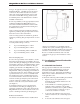
Choose a location for the unit which allows clearances
on all sides for maintenance and inspection. See Table 1.
Always install the unit on a rm, level surface.
The unit should not be located in an area where
leakage of any connections will result in damage to
the area adjacent to the appliance, or to lower oors
of the structure.
When this type of location is not available, install
a suitable drain pan, adequately drained, under the
appliance.
The appliance is design-certied by CSA-
International for installation on combustible
ooring; in basements; in utility rooms or alcoves.
MagnaTherm boilers must never be installed on
carpeting. The location for the appliance should
be chosen with regard to the vent pipe lengths and
external plumbing.
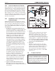
The unit shall be installed such that the gas ignition
system components are protected from water (dripping,
spraying, rain, etc.) during operation and service
(circulator replacement, control replacement, etc.).
When vented vertically, the MagnaTherm must be
located as close as practical to the vertical section
of the vent. If the vent terminal and/or combustion
air terminal terminate through a wall, and there is
potential for snow accumulation in the local area, both
terminals should be installed at an appropriate level
above grade or the maximum expected snow line.
The dimensions and requirements that are shown in
Table 1 should be met when choosing the locations
for the appliance.
2.2 Correct Vent Distance from
Outside Wall or Roof Termination
The forced draft combustion air blower in the
appliance has sufcient power to vent properly when
the guidelines in Table 2 are followed.
1.7 Unpacking
The MagnaTherm is shipped in a single crate.
Remove all packing and tie-down materials.
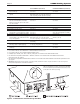
Note - When located on the same wall, the
MagnaTherm combustion air intake terminal must be
installed a minimum of 12” (30cm) below the exhaust
terminal. There must also be a minimum horizontal
distance from intake to the exhaust terminal
of 84” (213cm) See Figure 4
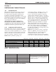
APPLIANCE SUGGESTED SERVICE ACCESS CLEARANCE
SURFACE INCHES CM
Front 24 61
Left Side 8 20
Right Side 8 20
Back 24 61
Top, 2000 12 30
Top, 2500 & 3000 15 38
Top, 4000 24 61
APPLIANCE REQUIRED CLEARANCE TO COMBUSTIBLES
SURFACE INCHES CM
Front 18 45
Left Side 4 15
Right Side 4 15
Back 11 15
Top 1 2.5
Vent 1 2.5
Table 1. Clearances
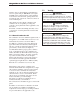
INTAKE / EXHAUST
MAX EQUIVALENT
SIZE DIAMETER FT. M
2000 & 2500 8” 100 30
3000 & 3500 10” 100 30
4000 12” 100 30
Installations in the U.S. require exhaust vent pipe that is CPVC
complying with ANSI/ASTM D1785 F441, polypropylene
complying with ULC S636, or stainless steel complying with
UL1738. Installations in Canada require exhaust vent pipe that
is certied to ULC S636.
Intake (air) pipe must be PVC or CPVC that complies with
ANSI/ASTM D1785 F441, ABS that complies with ANSI/ASTM
D1527, stainless steel, or galvanized material.
To calculate max equivalent length, measure the linear feet of
the pipe, and add 5 feet (1.5 m) for each elbow used.
Table 2. Vent / Air Pipe Sizes