
Installation, Operation and Maintenance Instructions User guide


MagnaTherm Boilers and Water Heaters
Page 11
Category IV appliances. Per the requirements of
CAN/CSA-B149.1, only BH vent systems can be
connected to these units and such vent systems,
either ULC S636 certied stainless steel or other
ULC S636 certied BH vent (eg. plastics) must
be installed per the vent manufacturer’s certied
installation instructions.
It is the responsibility of the appropriately licensed
technician installing this MagnaTherm to use
ULC S636 certied vent material consistent with
the requirements as described in the Venting and
Combustion Air section.
Class I venting systems are suitable for gas-red
appliances producing ue gas temperature of more
than 135°C, but not more than 245°C.
Class II venting systems are suitable for gas-red
appliances producing ue gas temperatures of 135°C
or less.
Class II venting systems are further classied into
four temperature ratings as follows:
A Up to and including 65°C / 149°F
B Up to and including 90°C / 194°F
C Up to and including 110°C / 230°F and
D Up to and including 135°C / 275°F
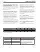
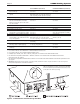
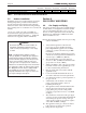
Flue Gas Sampling Port -
It is also the responsibility of the installer to ensure
that a ue gas sampling port is installed in the vent
system. This ue gas sampling port must be installed
near the ue connection of the MagnaTherm: within
2 feet of the ue connection. There is no ue gas
sampling port internal to the MagnaTherm, so one
must be installed in the vent system external to the
MagnaTherm. A ue gas sampling port available as
a component of the ULC S636 certied vent system
is preferred. However, if one is not available with
the certied vent system, LAARS suggests using
a tee with the branch connection sized to allow for
insertion of a ue gas analyzer probe. The branch
connection must be resealable with a cap or other
means to ensure the vent system remains sealed.
(See Figure 2)
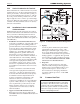
Consideration must be given to the placement
and orientation of the ue gas sampling port to
ensure that condensate is free to ow back into the
MagnaTherm and not collect anywhere in the vent
system - including in the ue gas sampling port.
Exhaust Vent Terminal -
An exhaust vent terminal must be installed. If an
exhaust vent terminal is not available with the
certied vent system, LAARS suggests the use of
a coupler tting from the certied vent system into
which the vent terminal screen can be installed.
Be sure to install and terminate both vent and
combustion air pipes per the instructions in this
section.
3.3 Locating the Vent and Combustion
Air Terminals
3.3.1 Side Wall Vent Terminal
The appropriate LAARS side wall vent terminal
must be used. The terminal must be located in
accordance with ANSI Z223.1/NFPA 54 and
applicable local codes. In Canada, the installation
must be in accordance with CSA B149.1 or .2 and
local applicable codes.
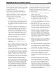
Consider the following when installing the terminal:
1. Figure 4 shows the requirements for
mechanical vent terminal clearances for the
U.S. and Canada.
2. Vent terminals for condensing appliances or
appliances with condensing vents are not
permitted to terminate above a public walkway,
or over an area where condensate or vapor
could create a nuisance or hazard.
3. Locate the vent terminal so that vent gases
cannot be drawn into air conditioning system
inlets.
4. Locate the vent terminal so that vent gases
Figure 2. Test Port