
Installation, Operation and Maintenance Instructions User guide


LAARS Heating Systems
Page 16
WARNING
Do not use open ame to check for leaks. An
open ame could lead to explosion, which
could result in property damage, serious injury
or death.
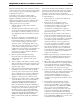
Note - The MagnaTherm appliance and all
other gas appliances sharing the gas supply line
must be ring at maximum capacity to properly
measure the inlet supply pressure. The pressure
can be measured at the supply pressure port
on the gas valve. Low gas pressure could be an
indication of an undersized gas meter, undersized
gas supply lines and/or an obstructed gas supply
line. MagnaTherm units may be equipped with
low and high gas pressure switches that are
integrally vent limited. These types of devices do
not require venting to atmosphere.
Section 4
GAS SUPPLY AND PIPING
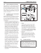
4.0 Gas Supply and Piping
Gas piping should be supported by suitable hangers
or oor stands, not the appliance. Installers should
refer to local building and safety codes or, in the
absence of such requirements, follow the National
Fuel Gas Code, ANSI Z223.1 NFPA and/or CSA
B149.1 installation codes.
Review the following instructions before proceeding
with the installation.
1. Verify that the appliance is tted for the
proper type of gas by checking the rating
plate. MagnaTherm appliances are normally
equipped to operate at elevations up to 2000
feet (610m).
However, the appliance will function properly
without the use of high altitude modication at
elevations up to 10,000 feet (3050 m).
2. The maximum inlet gas pressure must not
exceed 13” W.C. (3.2kPa). The minimum inlet
gas pressure is 4” W.C. (1.0kPa).
3. Table 8 and Table 9 offer some gas pipe sizing
information. Refer to the applicable gas code
for more detailed sizing information.
4. Run gas supply line in accordance with all
applicable codes.
5. Locate and install manual shutoff valves in
accordance with state and local requirements.
6. A sediment trap must be provided upstream of
the gas controls.
7. All threaded joints should be coated with
piping compound resistant to action of
liqueed petroleum gas.
8. The appliance and its individual shutoff valve
must be disconnected from the gas supply
piping during any pressure testing of that
system at test pressures in excess of 1/2 PSIG
(3.45kpa).
9. The unit must be isolated from the gas supply
system by closing its individual manual shutoff
valve during any pressure testing of the gas
supply piping system at test pressures equal to
or less than 1/2 PSIG (3.45kpa).
10. The appliance and its gas connection must be
leak tested before placing it in operation.
11. Purge all air from gas lines
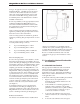
3.5 Outdoor Installation
If installing outdoors in a location that may experience
freezing temperatures, precautions must be taken to
prevent water in the heat exchanger and condensate
inside and outside of the boiler from freezing. Damage
due to freezing water or condensate is not covered by the
warranty.
For proper operation in outdoor installations,
the boiler must be equipped with the inlet air and
exhaust terminal kits listed in Table 7. Additional
instructions are supplied with the terminal kits.
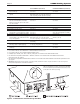
Table 7. Air & Vent accessories for Units Placed Outdoors
(Place in section 3.1)
Model 2000 Model 2500 Model 3000 Model 3500 Model 4000
Screen for horizontal galvanized air pipe D2012101 D2012101 D2012102 D2012103 D2012103
Screen for horizontal PVC air pipe CA012001 CA012001 CA012002 CA012003 CA012003
Screen for horizontal polypropylene air pipe CA012201 CA012201 CA012202 CA012203 CA012203
Screen for vertical galvanized air pipe D2012201 D2012201 D2012202 D2012203 D2012203
Screen for vertical PVC air pipe CA012401 CA012401 CA012402 CA012403 CA012403
Screen for vertical polypropylene air pipe CA012601 CA012601 CA012602 CA012603 CA012603
Table 3a - Ducted Air Accessories
(Place in section 3.2)
Model 2000 Model 2500 Model 3000 Model 3500 Model 4000
Horizontal vent terminal for stainless steel D2012001 D2012001 D2012002 D2012003 D2012003
Screen for horizontal CPVC vent CA012101 CA012101 CA012102 CA012103 CA012103
Screen for vertical stainless steel vent D2012301 D2012301 D2012302 D2012303 D2012303
Screen for vertical CPVC vent CA012501 CA012501 CA012502 CA012503 CA012503
Table 3* - Vent Accessories
(Place in section 3.5)
Model 2000 Model 2500 Model 3000 Model 3500 Model 4000
Air intake screen for unit placed outdoors CA011901 CA011901 CA011902 CA0011903 CA0011903
Vent terminal for unit placed outdoors CA011801 CA011801 CA011802 CA011803 CA011803
Table 3** - Air & Vent Accessories for Units Placed Outdoors