
Installation, Operation and Maintenance Instructions User guide


LAARS Heating Systems
Page 58
9.10 Vari-Prime
Vari-Prime is a variable pump control that is
standard equipment on all MGH boilers. Pump speed
is controlled to maintain a user-chosen temperature
rise between the inlet and outlet of the MagnaTherm.
General PCB Operation
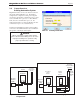
1. The desired Delta T can be set to any of the
following values by moving or adding jumpers to the
JP2 terminal on the control: See Figure 30
-15 deg F/8 deg C
-20 deg F/10 deg C
-25 deg F/13 deg C
-30 deg F/ 16 deg C
By adding a second jumper, one on “15 deg F” and
one on “20 deg F”, it is possible to achieve 35 deg F
/19 deg C.
By adding a second jumper, one on “15 deg F” and
one on “25 deg F”, it is possible to achieve 40 deg
F/22 deg C.
2. As shipped, the Vari-Prime has a jumper on
the JP4 terminal, to operate a 0-10 VDC output. If a
4-20 mA output is needed, move the jumper to the
JP5 terminal. Figure 30
3. Vari-Prime can operate in °F or °C. A jumper
on the JP1 terminal allows the user to choose the
temperature scale.
4 If Main Gas valve is “OFF” AND a call for heat
is “TRUE” then the PCB overrides the PID control
and runs the pump output at 100% (10 VDC, or 20
mA).
5. Once the Main Gas valve is energized the PCB
will maintain pump output at 100% for 60 seconds
to allow the system to stabilize. Once the 60 second
timer has expired, the PCB will then run the pump
output speed based on the jumper setpoint. .
6. When “T-T” is satised, the PCB will run pump
at 100% output for the duration of the pump overrun
time.
7. A jumper on the “JP1” terminal on the Vari-
Prime PCB will allow the Vari-Prime to operate
in degrees Fahrenheit or Celsius. (Factory set for
Fahrenheit).
8. The Vari-Prime PCB has a low end cap to
prevent nuisance low ow trips. The cap is factory
programmed to 2 VDC.
9. Factory settings are:
-Degrees - Fahrenheit
-Output Signal- 0 -10VDC
-Delta T setpoint - 30 °F/17 °C
2
6
4-20MA(-)
4-20MA(+)
0-10VDC(+)
0-10VDC(-)
N/C
COM
N/O
TB2
TB5
TB4
TB1
TB6
PCB
DIGITIZED
P/N E2345200
LED1
1
2
3
4
1
2
3
4
1
2
3
4
TB3
JP1
7&8 = F
1&2 = SPARE JUMPER
JP2
1&2 = 15 DEG F / 8 DEG C
3&4 = 20 DEG F / 10 DEG C
5&6 = 25 DEG F / 13 DEG C
7&8 = 30 DEG F / 16 DEG C
JP5
JP4
JP3
1
2
3
4
1
2
3
2
4
6
8
1
3
5
7
1
3
5
7
2
4
6
8
+24V
-24V
10K
INLET
SENSOR
10K
OUTLET
SENSOR
NOTE(S)
1.PURCHASED FROM DIGITIZED COMM. INC.
SERIAL NO. DC1002713
FIRMWARE SETTINGS
P = 20
I = 10
D = 0
ANTI RESET WINDUP = 600
CONTROL ERROR = 70
1
2
DWG NO.
E23452
SH
1
REV
A
AL 1-10-14
REVISIONS
REV.
CHANGE:
APPR
ENGR APPR
ECN
DRAFT
CHECK
UPDATED DRAWING PER SKETCH FROM LAB
A
14-002N-08
SM 1-10-14
SCALE: NONE
INTENDED SIZE:
SOFTWARE
DWG. NO:
C
SHEET 1 OF 1
REV.
APPROVALS
DRAFT
ENGR
APPR
UNLESS OTHERWISE SPECIFIED:
DO NOT SCALE DRAWING.
THIRD ANGLE PROJECTION.
DIMENSIONS ARE IN INCHES.
TOLERANCES ARE:
MATERIAL:
FINISH
CJT 12/2/11
S
DECIMALS .X
.1
DECIMALS .XX
.03
DECIMALS .XXX
.010
ANGLES
1
TITLE:
FRACTIONS
1/8"
DIGITIZED PRINTED CIRCUIT
BOARD
E23452
A
Figure 30. Vari-Prime Digital Circuit Board