
Installation, Operation and Maintenance Instructions User guide


MagnaTherm Boilers and Water Heaters
Page 65
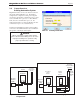
connecting the boiler to the main gas supply line.
Remove the front doors of the boiler, and the top
panels, to gain access to the gas valve and fuel/air
mixer. Disconnect the four ange bolts connecting
the gas manifold pipe to the gas valve. Remove the
electrical connections to the gas valve. Remove
the bolts connecting the fuel/air mixer ange to the
blower. This allows the entire gas valve and fuel/
air mixer assembly to be removed as an assembly to
facilitate inspection and cleaning.
After the valve has been removed, reassemble in
reverse order making sure to include all gaskets and
O-rings. Turn on the manual gas valves and check
for gas leaks. Turn on the main power. Place the unit
in operation following the instructions in Section 10.
Once the boiler is operating, check for leaks again
and conrm all fasteners are tight.
Check the setup for the unit according to the
instructions in Section 9.
11.2.3 Controller
Each MagnaTherm has an integrated controller
that incorporates manual reset high limit control,
operating temperature control, modulating control,
ignition control, outdoor reset control, pump control
and many other features. If any of these features are
thought to be defective, please consult the factory for
proper troubleshooting practices before replacing a
control.
If it is necessary to replace a controller, turn off
all power to the unit and shut off all manual gas
valves to the unit. Open the front doors to the unit.
Remove all wire connections from the control
board. The control board connections are keyed to
only allow connection in the proper location, but
proper handling techniques should be used to avoid
damage to the wiring or connectors. To remove the
control, undo the mounting screws. To replace the
control repeat the steps listed above in the reverse
order making sure to connect all wires in the proper
locations. Place the unit in operation following the
steps outlined in Section 10.
11.2.4 Hot Surface Ignitor
The ignitor equipped in MagnaTherm is a silicone-
nitride ceramic encased hot surface ignitor. The
silicone-nitride element is extremely fragile and
should be handled with care in the event of removal
(never touch the silicone-nitride tip with bare skin,
oils in your skin can cause damage and failure
upon heat up. To verify a defective ignitor the cold
resistance of the wires can be measure to be in the
range of 9-17 oHms if the ignitor is good, and zero
oHms would indicate a defective ignitor.
11.2.5 Flame Sensor
The ame sensor is a single rod system. The
minimum ame signal that will allow the unit to re
is 0.8 volts. To replace the ame sensor electrode,
shut off the power supply to the boiler. Turn off
all manual gas valves connecting the boiler to the
main gas supply line. Open the front doors of the
boiler to gain access to the ame sensor electrode.
Remove the ame sensor wire from the electrode.
Remove the two nuts fastening the electrode to the
burner plate. Remove and replace the old ame
sensor gasket. If the old electrode is determined to
be defective, reinstall a new ame sensor electrode
in the reverse order.
Caution
The igniters and sensors get become very hot.
If you touch these parts accidentally, this can
cause burns or injury.
11.2.7 Blower
The combustion air blower is a high pressure
centrifugal blower with a variable speed motor
driven by a factory installed VFD located in the high
voltage box. The speed of the motor is determined
by the controls logic which is delivered to the VFD
by a 0-10VDC signal. Even with the unit powered
up and a call for heat off, the VFD is still supplying
voltage to the blower motor but at 0 HZ. Main
Power MUST be disconnected before any attempt is
made to service the blower.
If it is necessary to replace or remove the blower,
turn off main power, remove hardware that connects
the Fuel/Air mixer to the blower, then remove the
hardware that connects the blower to the adapter
plate. If the fan is determined to be defective,
replace the existing fan with a new one by reversing
the steps listed above. Be sure to install all the
required gaskets and o-rings between blower,
adapter plate, and Fuel/Air mixer.
11.2.8 Heat Exchanger Tubes
Black carbon soot buildup on the external surfaces
of the heat exchanger is caused by one or more of