Installation and Operation Instructions Document 1230D Installation and Operation Instructions for MASCOT ® II Wall-Mounted Modulating Boiler Model LMH 125 MBTU/h Combination Boiler and Water Heater Model LMC 125 MBTU/h FOR YOUR SAFETY: This product must be installed and serviced by a professional service technician, qualified in hot water boiler and heater installation and maintenance.
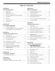
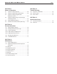
LAARS Heating Systems TABLE OF CONTENTS SECTION 1. General Information SECTION 6. Water Connections 1.1 Introduction ......................................................... 2 6.1 Central Heat System Piping.............................. 15 1.2 Rating Plate......................................................... 2 6.2 Cold Water Make-Up......................................... 15 1.3 Model Nomenclature........................................... 2 6.3 Freeze Protection.........................
Page 1 Mascot II Boilers and Water Heaters SECTION 9. Modes of Operation SECTION 12. Trouble Shooting 9.1 Hydronic Heating Demand................................ 28 12.1 Sequence of Operation . ................................... 35 9.2 Hydronic Heating with Outdoor Reset............... 28 12.2 Short Cycling..................................................... 35 9.3 Hydronic Heating Using External Modulation Control............................................ 28 12.3 Error Codes.............
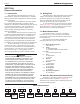
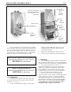
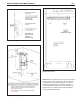
LAARS Heating Systems Page 2 SECTION 1. General Information 1.2 Rating Plate 1.1 Introduction The Rating Plate contains Manufacture Date, Model Number, Serial Number, Output Rating, and all other information pertaining to your Mascot II. The Rating Plate is located behind the center panel which will not open until the lower front panel is opened first. To open the Mascot II, first loosen the two phillips screws (see Figure 1A) and then open the front bottom panel downward.
Page 3 Mascot II Boilers and Water Heaters 5. THE TOP START UP / SHUT DOWN PANEL THEN INSTRUCTION (DECAL) SLIDES IS ON THE BACK OF THE UPWARD TOP COVER AND OFF 4. TWO MORE SCREWS RATING PLATE 3. FOLD USER INTERFACE CENTER PANEL DOWNWARD 1. LOOSEN THESE TWO SCREWS 2. FOLD BOTTOM PANEL DOWNWARD Figure 1A.
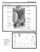
LAARS Heating Systems Page 4 1.7 Appliance Overview SHOWN WITH SEVERAL PANELS COMPLETELY REMOVED Figure 1B. Location of Components. 1) PRV, 30 PSI 5) Exhaust terminal assy 2) PRV Pipe w/ washer 6) Air intake terminal assy 3) Wall attach bracket 7) Ball valve 4) Outdoor sensor 8) System sensor (not shown) 9) Flow restrictor (not shown) Figure 2. Contents of Shipping Package.
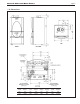
Page 5 Mascot II Boilers and Water Heaters 1.8 Dimensions Cond. Outlet Hydronic Return DHW Inlet 2nd Return Gas Supply Hydronic Supply DHW Outlet 2nd Supply 3/4" PVC 3/4" copper 1/2" NPT 3/4" copper 1/2" NPT 3/4" NPT 1/2" NPT 3/4" copper Figure 3. Dimensional Drawing.
LAARS Heating Systems Page 6 SECTION 2. Locating the Appliance 2.1 Locating the Appliance Mascot II is for indoor, wall-mounted installations only. The appliance should be located to provide clearances on all sides for maintenance and inspection. It should not be located in an area where leakage of any connections will result in damage to the area adjacent to the appliance or to lower floors of the structure.
Mascot II Boilers and Water Heaters Page 7 Note: Mascot II bracket and wall bracket are purposely offset. Figure 5. Mounting Detail. (Minimum) Zero clearance is allowed to combustible surfaces. However, the above minimum service clearances are strongly recommended. Closet installations require minimum air ventilation (see Section 3). Figure 4. Locating the Appliance. Figure 6. Wall Template (not to scale). Full-size template is included with the unit.
LAARS Heating Systems Page 8 SECTION 3. Venting and Combustion Air Laars Mascot II includes a standard CPVC vent/combustion air adapter. If field connections require use of PVC/ CPVC vent materials, the installer must use proper adhesive to join CPVC and/ or PVC pipe and fittings. 3.
Page 9 Mascot II Boilers and Water Heaters shall also be supplied for ventilation, including air required for comfort and proper working conditions for personnel. 3.2 Venting (Exhaust) WARNING Failure to use the appropriate vent material, installation techniques, glues/sealants could lead to vent failure causing property damage, personal injury or death. WARNING All venting must be installed according to this manual and any other applicable local codes, including but not limited to, ANSI Z223.
LAARS Heating Systems Page 10 IMPORTANT NOTE ABOUT COMMON VENTING: A single vent that is shared by multiple Mascot II units MUST be engineered by a competent venting specialist, and involves the selection of draft inducing equipment, hardware and controls to properly balance flue gas pressures. Do not common vent Mascot II units unless the vent system meets this requirement. Mascot II units are never permitted to share a vent with Category I appliances. 3.3 Locating Vent & Combustion Air Terminals 3.3.
Page 11 Mascot II Boilers and Water Heaters U.S. Installations (see note 1) Canadian Installations (see note 2) A= Clearance above grade, veranda, porch, deck, or balcony 12 inches (30 cm) See note 6 12 inches (30 cm) See note 6 B= Clearance to window or door that may be opened Direct vent only: 12 inches (30cm); Other than Direct vent: 4 ft (1.
LAARS Heating Systems Page 12 Massachusetts In Massachusetts the following items are required if the side-wall exhaust vent termination is less than seven (7) feet above finished grade in the area of the venting, including but not limited to decks and porches. From Massachusetts Rules and regulations 248 CMR 5.08 1.
Mascot II Boilers and Water Heaters Follow the lighting instructions. Adjust thermostat so the appliance will operate continuously. 5. Test for spillage at the draft hood relief opening after 5 minutes of main burner operation. Use the flame of a match or candle, or smoke from a cigarette, cigar or pipe. 6.
LAARS Heating Systems Page 14 SECTION 4. Gas Supply and Piping MASCOT II NATURAL GAS REQUIRED 4.1 Gas Supply and Piping Gas piping should be supported by suitable hangers or floor stands, not the appliance. Review the following instructions before proceeding with the installation. 1. Verify that the appliance is fitted for the proper type of gas by checking the rating plate. Mascot II will function properly without the use of high altitude modification at elevations up to 10,000 feet (3050 m). 2.
Page 15 Mascot II Boilers and Water Heaters SECTION 5. Pump Capacity PRV Included with Mascot II 5.1 Mascot II Heating System Pump Capacity A Pressure Relief Valve is included with each Mascot II. The PRV must be installed prior to filling the system. Figure 11. Available Pump Head. Figure 12. DHW Connections with Anti-Scald Valve and Flow Restrictor. SECTION 6. Water Connections 6.
Page 16 LAARS Heating Systems Figure 13. Hydronic Piping — High and low temp zones with indirect water heater (LMH using internal 3-way). The boiler piping system of a hot water heating boiler connected to heating coils located in air handling appliances where they may be exposed to refrigerated air circulation, must be equipped with flow control valves or other automatic means to prevent gravity circulation of the boiler water during the cooling cycle.
Page 17 Mascot II Boilers and Water Heaters 6.5 Recognized Chemicals The following manufacturers offer glycols, inhibitors, and anti-foamants that are suitable for use in the Mascot II. Please refer to the manufacturers instructions for proper selection and application. 1. Sentinel Performance Solutions Group 2. Hercules Chemical Company 3. Dow Chemical Company 6.6 Hot Water Piping 6.6.
LAARS Heating Systems Page 18 INLET TEMPERATURE °F 50°F GPM 60°F 70°F TEMP RISE °F 1.0 100 90 81 2.0 90 83 79 3.0 78 76 68 4.0 59 56 51 INLET TEMPERATURE °C 10°C LPM 16°C 21°C TEMP RISE °C 4 56 50 45 8 50 46 44 11 43 42 38 15 33 31 28 Caution Scalding Risk: Laars recommends the use of a thermostatic mixing valve at domestic hot water outlet (boiler location) to reduce potential for scalding.
Page 19 Installer to provide DHW (anti-scald) thermostatic mixing valve. Mascot II Boilers and Water Heaters Figure 16. Hydronic Piping — Multi boilers for large homes with long / multiple baseboard zones.
LAARS Heating Systems Installer to provide DHW (anti-scald) thermostatic mixing valve. Page 20 Figure 17. Hydronic Piping — Multi boilers for large homes with long / multiple radiant zones.
Page 21 Installer to provide DHW (anti-scald) thermostatic mixing valve. Mascot II Boilers and Water Heaters Figure 18. Hydronic Piping — Heating zones piped with zone pumps.
LAARS Heating Systems Installer to provide DHW (anti-scald) thermostatic mixing valve. Page 22 Figure 19. Hydronic Piping — Heating zones piped with zone valves.
Page 23 Mascot II Boilers and Water Heaters SECTION 7. Electrical Connections three-way valve if central heat) upon a call for heat. Once the call for heat is satisfied the pump will remain on for the defined pump overrun time. WARNING The appliance must be electrically grounded in accordance with the requirements of the authority having jurisdiction or, in the absence of such requirements, with the latest edition of the National Electrical Code, ANSI/ NFPA 70, in the U.S.
Page 24 b. c. d. e. 7.10 LAARS Heating Systems If there are more boilers in the system connect a wire from Modbus port 1 terminal A of boiler 2 to Modbus port 1 terminal A of boiler 3. Repeat these steps until all Modbus port 1 terminal A connections are wired. Repeat the above steps for Modbus port 1 terminal B and C connections to complete the wiring. Connect the drain wire from the twisted pair wire to ground on one end of the wire only.
R R K BK 3 WAY ATER FLOW VALVE P O BK R Y P R 1 R BK BK 2 13 BL T-T OR INTERLOCK 3 GR 5 14 Y BR DOMESTIC EMP. SENSOR ANALOG INPUT + Y BR R BR GR 2 1 P BL O 3 1 4 2 BLINLET OUTLET TEMP. GR TEMP. SENSOR SENSOR R GR 2 1 6 3 Y 13 654 321 J4B 5 4 J1 3 1 4 2 J2 J8A GR SYSTEM SENSOR DOMESTIC EMP.
LAARS Heating Systems Page 26 SECTION 8. Control Setup and Operation MENU ITEM The Mascot II control is an integrated electronic control that replaces many of the individual components found on older appliances. The control acts as the ignition control, pump control, high limit and cascading/ lead lag control and is setup using the digital display on the appliance.
Page 27 Mascot II Boilers and Water Heaters 8.2 Ignition Control- Sequence of Events 1. 2. 3. 4. 5. Call for heat Safety chain check Fan starts. Prepurge timer is started. Pre ignition time of 2 seconds to check the flame sensor operation and status. 6. Trial for ignition period, 4 seconds. The direct spark ignition switches to constant spark for three seconds, during which time the gas valve is open.
LAARS Heating Systems Page 28 on when the water temperature reaches 115°F. Set the hysteresis values to match the boiler to the system operating characteristics. Setting this value correctly will help reduce the chance of short cycling. 8.8.5 Lead Lag Base Load Setting The lead lag system uses a base load setting that is set through the "setup" menu called "bL".
Page 29 Mascot II Boilers and Water Heaters water temperatures. The boiler setpoint is used to limit the maximum water temperature leaving the boiler only. The modulation rate is controlled by a 4-20mA (010Vdc using converter) signal supplied by an external control. When setting up a system using an external control care must be taken to set the external control algorithms to prevent the boiler from short cycling or "hunting " to prevent premature component failure.
Page 30 SECTION 10. Set Up Instructions 10.1 Filling the Boiler System 1. 2. 3. 4. 5. 6. Ensure the system is fully connected. Close all bleeding devices and open make-up water valve. Allow system to fill slowly. Move manual lever on 3-way valve actuator to "open" position, allowing air to purge from boiler loop. Valve is normally in DHW position until there is a call for Central Heat via "T-T" contacts.
Page 31 Mascot II Boilers and Water Heaters 4. 5. 6. Mascot II will enter the start sequence. Blower and pump will energize for pre-purge, then the ignition sequence starts. After all safety devices are verified, the gas valve opens. If ignition doesn’t occur, turn off the Mascot II, check that there is proper gas supply. Wait 5 minutes and start the unit again. Turn Mascot II on.
LAARS Heating Systems Page 32 Gas Supply Line Manifold Pressure Screw (under cap) O-Ring Propane Gas Orifice High-fire setting Note: H igh and Low Fire CO2 settings should be approximately equal. Figure 25. Adjustment Screws and Settings for CO2 MANIFOLD GAS TYPE CO2 (%) RANGE PRESSURE (inH20) Natural Propane 8.8 __ 9.8 9.8 __ 10.8 3.5 __ 4.5 3.5 __ 4.5 Table 13. CO2 Range and Pressure Settings.
Page 33 Mascot II Boilers and Water Heaters SECTION 11. Maintenance WARNING Disconnect all power to the appliance before attempting any service to the appliance. Contact with electricity can result in severe injury or death. 11.1 System Maintenance 1. 2. 3. 4. 5. 6. 7. 8. 9. (yearly, unless otherwise noted) If a strainer is employed in a pressure reducing valve or the piping, clean it every six months. Inspect the venting system for obstruction or leakage at least once a year.
LAARS Heating Systems Page 34 11.2.4 Flame Sensor The flame sensor is a single rod system. To replace the flame sensor electrode, shut off the 120 Volt power supply to the boiler. Turn off all manual gas valves connecting the boiler to the main gas supply line. Remove the front door of the boiler to gain access to the flame sensor electrode. Remove the flame sensor wire from the electrode. Remove the two bolts fastening the electrode to the burner doors. Remove and replace the old flame sensor gasket.
Page 35 Mascot II Boilers and Water Heaters complete installation of this kit. The installation is not proper and complete until the operation of the converted appliance is checked as specified in the manufacturer's instruction supplied with the kit. 18. Adjust as needed to achieve proper levels. Refer to sections 10.2.2 and 10.2.3 of this manual for the proper adjusting procedures. 19. Re-Install front covers.
LAARS Heating Systems Page 36 CODE# PROBLEM PROBABLE CAUSE SOLUTION COMMON LOCKOUT CODES 27 Internal error Flame rod to ground Check wiring / probe grounded, dirty probe 47 Flame rod to ground leakage Faulty flame detector Clean or replace flame detector 49 24VAC voltage low/high Faulty transformer Check/correct supply line voltage; replace faulty transformer 52 Motor tachometer fault Check fan harness wiring for continuity; replace faulty 53 AC inputs phase reversed 6
Page 37 Mascot II Boilers and Water Heaters CODE# PROBLEM PROBABLE CAUSE SOLUTION ALERT CODES was reached however the cycle count will not increment any higher than 999,999 cycles Replace controller or adjust the count using blue display 50 Maximum hours count was reached Control operates correctly, however the hours count will not increment any higher than 999,999 hours 248 CH outdoor temperature was invalid 25
LAARS Heating Systems Page 38 SECTION 13. Replacement Parts Use only genuine LAARS replacement parts. 13.1 General Information To order or purchase parts for the LAARS Mascot II, contact your nearest LAARS dealer or distributor. If they cannot supply you with what you need, contact Customer Service (see back cover for address, telephone and fax numbers). 13.
Page 39 Mascot II Boilers and Water Heaters ITEM DESCRIPTION BURNER COMPONENTS - see Figure 33 SIZE 125 ITEM DESCRIPTION PLUMBING COMPONENTS - see Figure 35 SIZE 125 1 Burner, main R2069102 P1 Tank, expansion, rect, 10 liter 2 Gasket, burner RS2108500 P2 Bracket weldment, expansion tank 3 Tile, refractory, front, combustion chamber RT2109000 P3 Grommet, pipe, wire, multi size, rubber 4 Ignitor, spark, w/gasket R2069300 P4 Pipe, gas 5 Flame sensor, w/gasket R2069200 P5 O-ring,
Page 40 Figure 28. Panel Assembly, Door Top.
Mascot II Boilers and Water Heaters Figure 29. Panel Assembly, Door Middle.
Page 42 Figure 30. Panel Assembly, Door Bottom.
Mascot II Boilers and Water Heaters Figure 31. Base Jacket Assembly.
Page 44 Figure 32. Heat Exchanger Cabinet, Fan.
Mascot II Boilers and Water Heaters Figure 33. Heat Exchanger Burner Components.
Page 46 LAARS Heating Systems 8X 8W (for propane only) Figure 34. Pump Assembly Components.
Mascot II Boilers and Water Heaters Figure 35. Plumbing Components.
Page 48 LAARS Heating Systems
Mascot II Boilers and Water Heaters Page 49
H2338100D Dimensions and specifications subject to change without notice in accordance with our policy of continuous product improvement. 800.900.9276 • Fax 800.559.1583 (Customer Service and Product Support) 20 Industrial Way, Rochester, NH 03867 • 603.335.6300 • Fax 603.335.3355 1869 Sismet Road, Mississauga, Ontario, Canada L4W 1W8 • 905.238.0100 • Fax 905.366.0130 www.Laars.com Litho in U.S.A.