
User Manual


LAARS Heating Systems
Page 10
IMPORTANT NOTE ABOUT COMMON VENTING: A
single vent that is shared by multiple Mascot II units
MUST be engineered by a competent venting specialist,
and involves the selection of draft inducing equipment,
hardware and controls to properly balance ue gas
pressures. Do not common vent Mascot II units
unless the vent system meets this requirement.
Mascot II units are never permitted to share a vent
with Category I appliances.
3.3 Locating Vent & Combustion Air
Terminals
3.3.1 Side Wall Vent Terminal
The appropriate Laars side wall vent terminal must
be used. The terminal must be located in accordance
with ANSI Z223.1/NFPA 54 and applicable local codes.
In Canada, the installation must be in accordance with
CSA B149.1 or .2 and local applicable codes. Consider
the following when installing the terminal:
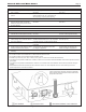
1. Figure 9 shows the requirements for mechanical
vent terminal clearances for the U.S. and Canada.
2. Vent terminals for condensing appliances or
appliances with condensing vents are not permitted
to terminate above a public walkway, or over an
area where condensate or vapor could create a
nuisance or hazard.
3. Locate the vent terminal so that vent gases cannot
be drawn into air conditioning system inlets.
4. Locate the vent terminal so that vent gases cannot
enter the building through doors, windows, gravity
inlets or other openings. Whenever possible, avoid
locations under windows or near doors.
5. Locate the vent terminal so that it cannot be
blocked by snow. The installer may determine
that a vent terminal must be higher than the
minimum shown in codes, depending upon local
conditions.
6. Locate the terminal so the vent exhaust does not
settle on building surfaces or other nearby objects.
Vent products may damage surfaces or objects.
7. If the boiler or water heater uses ducted
combustion air from an intake terminal located on
the same wall, see Figure 9 for proper spacing and
orientation.
If the vent termination is located in an area
exposed to high winds, an optional PVC tee (the same
diameter as the vent pipe) may be used. The tee'd vent
termination offers greater protection from wind related
operating issues.
3.3.2 Side Wall Combustion Air Terminal
The LAARS side wall combustion air terminal, or
concentric terminal (see Table 3), must be used when the
heater takes air from a side wall. Consider the following
when installing the terminal (see Figure 9):
1. Do not locate the air inlet terminal near a source
of corrosive chemical fumes (e.g., cleaning uid,
chlorine compounds, etc.)
2. Locate the terminal so that it will not be subject
to damage by accident or vandalism. It must be at
least 7 feet (2.1m) above a public walkway.
3. Locate the combustion air terminal so that it cannot
be blocked by snow. The National Fuel Gas Code
requires that it be at least 12 inches (30cm) above
grade, but the installer may determine it should be
higher, depending upon local conditions.
4. For concentric vent, follow instructions
included with vent kit.
5. Multiple vent kits should be installed such that the
horizontal distance between outlet group and inlet
group is 36" (90cm) minimum.
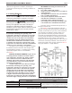
6. Vent outlet must be no lower than the center of
the air inlet, and must be at least 12" (30cm) away
from the air inlet (see Figure 8).
3.3.3 Vertical Vent Terminal
When the unit is vented through the roof, the vent
must extend at least 3 feet (0.9m) above the point at
which it penetrates the roof. It must extend at least 2 feet
(0.6m) higher than any portion of a building within a
horizontal distance of 10 feet (3.0m), and high enough
above the roof line to prevent blockage from snow.
When the combustion air is taken from the roof, the
combustion air must terminate at least 12" (30cm) below
the vent terminal (see Figure 7).
3.3.4 Vertical Combustion Air Terminal
When combustion air is taken from the roof, a
eld-supplied rain cap or an elbow arrangement must be
used to prevent entry of rain water (see Figure 7). The
opening on the end of the terminal must be at least 12"
(30cm) above the point at which it penetrates the roof,
and high enough above the roof line to prevent blockage
from snow. When the vent terminates on the roof, the
combustion air must terminate at least 12" (30cm) below
the vent terminal.
3.3.5 Installations in the Commonwealth of
Figure 8. Minimum Venting Distance.