Start Up Guide Document 1279 Start Up Guide for Mascot ® II Wall Mounted, Modulating Boiler Model LMH 125 MBTU/h and Combination Boiler and Water Heater Model LMC 125 MBTU/h
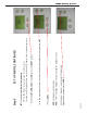
Page 1 Page 1 The word Outlet will appear in the top left corner of the display screen. After 90 seconds, the 3.6 flash code will time out and the display will then show the Outlet screen. Note; any time the power is turned off to the boiler and then restored, the flash code will appear for a 90 second period. Turn on power to the boiler. The system display will flash a code of 3.6. for 90 seconds. During this time, no set points or adjustments can be made.
Page 2 Page 2 •The Central Heat set point is now complete. Note: you must press the DONE button to store the set point. If you forget to press the DONE button, the control will go back to the default setting of 120 degrees. •When you reach the desired set point, press the DONE button on the lower left corner of the display For this example we are using 180 degrees. •Press the up arrow to increase the desired set point •120 degrees will appear on the screen.
Note: the boiler should not be running, so the Outlet & Inlet temp should be the same. Press the NEXT button once. Now the inlet temp will appear on the screen Page 3 Page 3 • Press the NEXT button again and DHW will appear on the screen • Press the NEXT button again. Delta T will now appear on the screen • • Starting in the outlet screen, you will see the word NEXT just above the lower right button. It is recommended on the Mascot II that a mixing valve be used.
DHW SET POINT, CONTINUED Page 4 Page 4 •After the desired set point is reached, press the DONE button Reminder: You must press the DONE button to store the set point. •Using the up arrow, increase the DHW set point to 150 degrees. NOTE: IF YOU ARE NOT USING A MIXING VALVE ON THIS SYSTEM, DO NOT INCREASE THE SET POINT ! •120 degrees will appear on the screen. This is the default setting.
The Fahrenheit symbol will now appear on the display. You are now in SET UP MODE. Press the NEXT button to advance to the next screen. This screen is used for outdoor reset. It is defaulted to OFF. If you are not using the outdoor reset function, then leave this screen OFF, press NEXT and proceed to page, Under RMT address. If you are using out door reset, press the up arrow and turn this feature ON. To use this feature, you must install the OUTDOOR SENSOR.
SET UP MODE, CONTINUED With the LBT, HOD,LOD screen ON, press the NEXT button Page 6 Page 6 Use the up or down arrows to select the desired high outdoor temperature (HOD), HOD will appear on the screen. HOD: This is the high outdoor set point used for outdoor reset. • Press NEXT. • Use the up or down arrows to select the desired low boiler temperature, LBT • Example: on a 65 degree day you may only need 120 degree boiler supply temperature. LBT: Stands for Low Boiler Temperature.
Page 7 Page 7 •RMT address: This should always be set for 1, unless cascading multiple boilers together. The number 1 will now appear on the screen. This is the RMT address. •Press NEXT button •Use the up or down arrows to select the desired low outdoor temperature (LOD), LOD: This is the low outdoor temperature set point used for the reset curve. It is recommended to set it 10 deg. F. above your degree day. LOD will now appear on the screen.
SET UP MODE, CONTINUED Page 8 Page 8 •HS stands for Hysteresis. This is the differential for the ON/OFF set point of the system loop. System sensor must be installed for this function. •Press NEXT • LL must always be left OFF unless using the cascading feature •Press the NEXT button •LL: Stands for Lead Lag. This feature is only used when cascading •With the RMT address of 1 on the screen.
bL: Stands for Base load. This feature is used for cascading Press the NEXT button 50% is the Base Load default before the next boiler fires in a cascading application • • • Page 9 Page 9 Press the NEXT button Example: If the LL set point is 180 degree and the (HS) is 5 degrees, the burner will shut off at 185 degrees. At 175 degrees, the burner will come back on. 5 degrees will appear on the display. This temperature can be adjusted but it is not recommended.
Sd is warm weather shut down. Press NEXT If Flashing, wait 30 seconds until flashing stops.
SET UP MODE, CONTINUED Page 11 Page 11 NOTE: YOU MUST PRESS DONE TO STORE THE CHANGES MADE IN THE SET UP MODE. •Now press DONE. •If an adjustment is needed, use the up arrow to adjust time ASC: stands for Anti Short Cycle time. It is defaulted on the Mascot for 0 minutes. This feature can be adjusted if a boiler is short cycling due to a small heating zone.
MASCOT II START UP Page 12 Page 12 • Shut off the gas supply. Using a small screwdriver, loosen the inlet set screw. Attach a hose from the manometer to the inlet test port. Turn on the gas supply. Measure the inlet static gas pressure. Do not remove the manometer. You will need to measure the gas supply pressure with the boiler running at high fire. If using outdoor reset, disconnect the outdoor sensor wires from terminals 5 & 6 during the start up.
Remove test plug and insert the analyzer in the flue opening provided With the boiler powered up, turn on ALL ZONES of heat With a call for heat, the system display will go through the firing sequence. The sequence will read: Check, then Prepurge, then Ignition and Run. You will need to adjust the CO2 percentage on both high and low fire. High fire should be checked first. This is done by adjusting the firing rate in Diagnostic mode .
Page 14 Page 14 NOTE: If the boiler is not firing, you will see --- on the display . If the boiler is running, you will get a reading. This reading will change depending on the rate of fire. • Press the NEXT button to advance to the next screen. The next screen will be the Alert screen symbol. The symbol will appear as uA. NOTE: The MAX Outlet is not adjustable. This is the fixed limit. Press NEXT and advance to the MAX Outlet screen. Press the NEXT button and it will advance to the Lock Out screen.
Page 15 Page 15 NOTE: The MAX Stack in not adjustable. This is the stack temperature limit. Press NEXT and advance to MAX Stack screen NOTE: You cannot adjust DHW in this screen. Press NEXT again. The screen will now flash 10%. Press NEXT and advance to a screen that reads MIN. **This screen is for minimum firing rate.** MASCOT II START UP, CONTINUED Press NEXT and it will advance to the DHW screen.
MASCOT II START UP, CONTINUED Page 16 Page 16 NEXT button again . The screen will now display MAX in the top right corner. Press the From the 10% (low fire) screen, press NEXT. With the boiler flashing 10%, you are now forced into LOW FIRE. The screen will flash 10% and the outlet temp. We recommend testing and adjusting the CO2 in HIGH FIRE first. Then, go back into LOW FIRE and make CO2 adjustments in 10% of firing rate.
MASCOT II START UP, CONTINUED Page 17 Page 17 After completing HIGH FIRE adjustment, go into the LOW FIRE screen and adjust low fire CO2. See next page. Low fire adjustment LOW FIRE ADJUSTMENT is under the large brass cap on the front of the valve. For low fire adjustment, you will need a 5/32 Allen key. HIGH FIRE ADJUSTMENT is the small flat-head screw at the top right side of the gas valve. With the combustion analyzer, check and adjust the CO2 high fire. The CO2 should be 9.
MASCOT II START UP, CONTINUED Page 18 Page 18 Turn the boiler on. Test both heat and DHW. Adjust the mixing valve in accordance with local code requirements. Reconnect the outdoor sensor to terminals 5&6. When finished, shut OFF the boiler, shut off the gas supply, remove the gas manometer and tighten the set screw on the gas valve. Turn on the gas supply and check for gas leaks. Make the proper low fire CO2 adjustments. The low fire CO2 adjustment on the Mascot II should equal the high fire CO2.
Notes: _______________________________________ _______________________________________ _______________________________________ _______________________________________ _______________________________________ _______________________________________ _______________________________________ _______________________________________ _______________________________________ _______________________________________ _______________________________________ _______________________________________ ________________________