
Install and Operating Manual User guide

Mascot II Boilers and Water Heaters
Page 23
SECTION 7.
Electrical Connections
WARNING
The appliance must be electrically grounded in
accordance with the requirements of the authority having
jurisdiction or, in the absence of such requirements, with
the latest edition of the National Electrical Code, ANSI/
NFPA 70, in the U.S. and with latest edition of CSA
C22.1 Canadian Electrical Code, Part 1, in Canada. Do
not rely on the gas or water piping to ground the metal
parts of the boiler. Plastic pipe or dielectric unions may
isolate the boiler electrically. Service and maintenance
personnel, who work on or around the boiler, may be
standing on wet oors and could be electrocuted by an
ungrounded boiler. Electrocution can result in severe
injury or death.
Single pole switches, including those of safety
controls and protective devices must not be wired in a
grounded line.
All electrical connections are made on the terminal
blocks that are located inside the control panel.
NOTE: All internal electrical components have been
prewired. No attempt should be made to connect
electrical wires to any other location except the terminal
blocks.
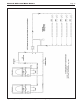
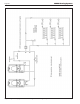
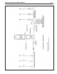
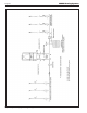
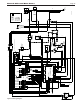
Wiring connections are shown in Figures 21-22.
Important Note: DO NOT MAKE/BREAK MASCOT II
LINE VOLTAGE TO SIGNAL CALL FOR HEAT. A “call
for heat / end call for heat” MUST be connected to the
eld interlock terminals. Some Mascot II components
are designed to have constant voltage during normal
operation. If the Mascot II's supply voltage is toggled
as a call for heat signal, premature failure of these
components may result.
If using remote 4-20mA control, Mascot II does not
recognize 4mA as a signal to shut off. If the call for heat
is not connected between the eld interlock terminals,
Mascot II will remain in low re when it sees 4mA as a
modulating signal.
Caution
Mascot II supply voltage must not be disengaged,
except for service or isolation, or unless otherwise
instructed by procedures outlined in this manual. To
signal a call for heat, use the 24V eld-interlock, as
shown in the wiring diagram(s).
7.1 Main Power
Plug power cord into a non-switched 115V
electrical outlet with 15A circuit protection. FLA is
2A. There is an internal 10A breaker to protect internal
system components.
7.2 Pump Connections
Mascot II energizes the integral boiler pump (and
three-way valve if central heat) upon a call for heat.
Once the call for heat is satised the pump will remain
on for the dened pump overrun time.
NOTE: System pump contacts are dry contacts.
Appropriate voltage must be supplied to the System
pump for proper operation.
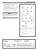
System pump connections are located in the
control panel (see Figure 20). The system pump contacts
are rated for 120Vac, 7.4 amps. To use the contacts,
power must be supplied on one terminal with the other
terminal wired to the pump or a relay controlling the
pump.
7.3 24Vac Transformer with Circuit Breaker
24Vac is supplied by a transformer mounted behind
the upper door. All 24Vac power is supplied
through a
2A circuit breaker located behind middle door.
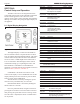
7.4 Central Heat - Call for Heat
Connect the Call for Heat to terminals #1 and #2
(connections labeled "T-T or interlock").
7.5 Outdoor Air Temperature Sensor
Connect the outdoor air temperature sensor
to connections labeled "Outdoor temp sensor." The
outdoor air temperature sensor is used for warm weather
shutdown and outdoor reset.
7.6 Domestic Hot Water Connection
For LMH and indirect water heater, connect
aquastat for remote sensor to terminals 7 & 8 (see
Figures 20 and 22).
7.7 System Sensor
(lead lag/cascading operation only)
Connect the system sensor to connections labeled
"system sensor."
7.8 External Control Connections
Connect 4-20mA signals from external controls
or building automation systems. When making the
connections, follow the polarity designations shown on
the label.
7.9 Lead Lag / Cascading Wiring
Connections
Connect each boiler in the cascade system together
by daisy chaining each control from Modbus port 1
(MB1) of the rst boiler to the second and so on. This
can be done using 22awg or thicker shielded twisted pair
wire with drain. Two twisted pairs or three conductors
are needed.
a. To daisy-chain the boilers connect a wire from
Modbus port 1 (MB1) terminal A of the rst boiler
to Modbus port 1 (MB1) terminal A of the second
boiler.