
Install and Operating Manual User guide

LAARS Heating Systems
Page 24
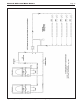
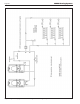
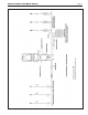
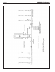
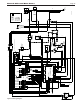
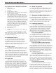
Figure 21. Ladder Diagram.
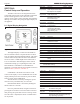
b. If there are more boilers in the system connect a
wire from Modbus port 1 terminal A of boiler 2 to
Modbus port 1 terminal A of boiler 3.
c. Repeat these steps until all Modbus port 1 terminal
A connections are wired.
d. Repeat the above steps for Modbus port 1 terminal
B and C connections to complete the wiring.
e. Connect the drain wire from the twisted pair wire
to ground on one end of the wire only.
7.10 Wiring Diagrams (see Figures 21-22)
Caution
Label all wires prior to disconnection when servicing
controls. Wiring errors can cause improper and
dangerous operation. Verify proper operation after
servicing
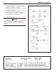
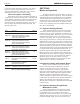
Figure 20. System Pump Connections on Control Panel.