
Install and Operating Manual User guide

Mascot II Boilers and Water Heaters
Page 29
water temperatures. The boiler setpoint is used to limit
the maximum water temperature leaving the boiler only.
The modulation rate is controlled by a 4-20mA (0-
10Vdc using converter) signal supplied by an external
control. When setting up a system using an external
control care must be taken to set the external control
algorithms to prevent the boiler from short cycling or
"hunting " to prevent premature component failure.
NOTE: A call for DHW will override external control.
9.4 Hydronic Heating Using Local Lead-
Lag/Cascading Feature
When using single or multiple Mascot II's in lead-
lag conguration, the system sensor is used to monitor
the demand and modulation rates of the operating
system (see Section 7 for wiring instructions).
Let’s consider the following example:
Three Mascot II boilers (let’s call them “Lead”,
“Slave1” and “Slave2”) tied together via Modbus
1 connection, with appropriate RMT Address (1, 2,
3). System sensor input is used to indicate common
secondary loop temperature.
System setpoint = 150°F
HS (hysteresis) = 10°F (default)
BL (base load) = 50% (default)
Anti-short-cycle = 5 minutes
Run sequence is initiated when system temperature
falls to 140°F (setpoint less hysteresis value). Lead
boiler will start. All ring rates will depend on several
application characteristics, including ow rate, system
load, water volume, etc. Boilers will start at a rate of
35%. If the load is such that Lead’s rate increases to
50%, “Slave1” will go through its startup sequence and
begin ring at 35%. At this point, both boilers (Lead and
Slave1) will continue to respond simultaneously to the
load/system characteristics, by modulating up or down
together, in relation to the relative system setpoint and
load characteristics.
Scenario 1: If the system loop temperature rises quickly,
and moves above setpoint, then the boilers will
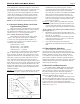
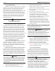
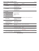
Figure 24. Outdoor Reset Setpoint Temperatures.
simultaneously drop their ring rate. If when
reaching the point where both boilers drop toward
their minimum ring rate (20%), then the rst
slave will drop out. Slave1 will remain unavailable
until its ASC timer has expired (5 minutes). If
the load were to increase such to drive all active
boilers to 50% ring rate or more, during the ASC
time, Slave2 will begin its startup sequence and
begin to re at 35%, etc.
Scenario 2: If the system loop temperature continues
to drop (load increases), then the two boilers will
increase ring rate together. At 50%, Slave2 will
begin its ring sequence and be added to the group.
All three boilers will continue to re simultaneously at
equal input rates or…
1. Modulation rate approaches minimum ring rate
(20%), in which case Slave2 will rst drop out, and
then Slave1, accordingly.
2. System temperature reaches 10°F (HS- hysteresis
value) above setpoint (e.g. 160°F), in which case
remaining boiler will shut off.
3. Any of the boilers approach its high limit
temperature the individual boiler will modulate
back.
9.5 Warm Weather Shutdown
Warm weather shutdown overrides a central
heat call for heat when the outdoor air temperature is
greater than the warm weather shutdown setpoint. Warm
weather shutdown is always active whenever there
is an outdoor sensor attached to the control. To avoid
warm weather shutdown the warm weather shutdown
temperature should be increased as necessary. The warm
weather shutdown setpoint can be adjusted in SETUP
mode, using the SD menu.
9.6 Domestic Hot Water Demand
For Combi (LMC), DHW demand is triggered by
a ow switch located near the DHW cold water inlet.
When water begins to ow (open faucet, shower, etc.),
the boiler will re, based on the water temperature
requirements. It may cycle on and off under very low
ow rates. Minimum ow is 0.5 gpm.
For LMH, an optional indirect water heater can be
piped-in using Mascot's integral 3-way valve as a zone
valve. An aquastat in the indirect water heater connected
in place of the ow switch will signal demand for
DHW. The service person should note the minor wiring
differences on Figure 22.