
Install and Operating Manual User guide

Mascot II Boilers and Water Heaters
Page 31
4. Mascot II will enter the start sequence. Blower
and pump will energize for pre-purge, then the
ignition sequence starts. After all safety devices
are veried, the gas valve opens. If ignition doesn’t
occur, turn off the Mascot II, check that there is
proper gas supply. Wait 5 minutes and start the unit
again.
5. Turn Mascot II on.
6. After placing the appliance in operation, the
Burner Safety Shutoff Device must be tested:
(a) Close gas shutoff valve with burner
operating.
(b) Flame will go out and blower will continue
to run for the post purge cycle. One or three
additional attempts to light will follow
including pre-purge, ignitor on, valve/ame
on and post purge. Ignition will not occur
as the gas is off. The ignition control will
lockout.
(c) Open gas shutoff valve. Reset the boiler
control by pressing the RESET button on
the control or on the display. Restart the
appliance. The ignition sequence will start
again and the burner will start. The appliance
will return to its previous mode of operation.
Caution
Should any odor of gas be detected, or if the gas
burner does not appear to be functioning in a normal
manner, CLOSE MAIN SHUTOFF VALVE. Do not
shut off switch. Contact your heating contractor, gas
company, or factory representative.
10.2.2 Boiler Setup and Adjustment
1. Measure the CO
2
in the ue products at high re.
The Mascot II can be forced to high re to allow
for easier setup. Refer to Section 8.1, Table 11
for instructions on how to access the forced rate
menu. The CO
2
readings should be between the
range shown in Table 13. If the CO
2
is not within
the range shown, adjustments may be made.
To adjust the high re CO
2
, locate the high re
adjuster screw according to the appropriate gure.
Slowly make adjustments in 1/16 of a revolution
increments until the CO
2
is within the range
identied.
2. Measure the CO
2
in the ue products at low re.
Mascot II can be forced to low re to allow for
easier setup. Refer to Section 8.1, Table 11 for
instructions on how to access the forced rate menu.
CO
2
readings should be between the range shown
in Table 13. If the CO
2
is not within the range
shown, adjustments may be made. To adjust the
low re CO
2
, locate the low re adjuster screw
according to the appropriate gure. Slowly make
adjustments in 1/16 of a revolution increments
until the CO
2
is within the range identied
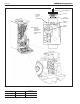
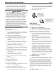
(see Figure 25).
3. Repeat steps 1 and 2 to conrm that the CO
2
ranges are within the required ranges. High and
Low Fire CO2 settings should be approximately
equal. Adjust if necessary.
If any your CO2 readings cannot be adjusted
to the specied ranges (see Table 13), please
consult the factory for further information.
10.2.3 Manifold Pressure Check
1. Remove the cap that covers the manifold pressure
screw (See Figure 25). Loosen the manifold pressure
screw one revolution, and attach manometer.
2. Check Manifold pressure at high re using
manometer (see Table 13 for pressure range).
3. When nished, remove manometer, tighten screw,
and replace the cap.
If your pressure reading is not within the
specied range (see Table 13), please consult the
factory for further information.
WARNING
Improper adjustment may lead to poor combustion
quality, increasing the amount of carbon monoxide
produced. Excessive carbon monoxide levels may
lead to personal injury or death.
10.3 Shutting Down Mascot II
1. Turn off the main electrical disconnect switch.
2. Close all manual gas valves.
3. If freezing is anticipated, drain Mascot II and be
sure to also protect building piping from freezing.
All water must be removed from heat exchanger
and condensate trap or else damage from freezing
may occur.
This step to be performed by a qualied service person.
10.4 To Restart Mascot II
If drained, follow Section 10.1 in this manual
for proper lling and purging.
1. Turn off the main electrical disconnect switch.
2. Close all manual gas valves.
3. WAIT FIVE (5) MINUTES.
4. Set the aquastat or thermostat to its lowest setting.
5. Open all manual gas valves.
6. Reset all safety switches (pressure switch, manual
reset high limit, etc.).
7. Set the temperature controller to the desired
temperature setting and switch on electrical power.
8. Burner will go through a prepurge period and
ignitor warm-up period, followed by ignition.