
Install and Operating Manual User guide

Mascot II Boilers and Water Heaters
Page 33
SECTION 11.
Maintenance
WARNING
Disconnect all power to the appliance before
attempting any service to the appliance. Contact with
electricity can result in severe injury or death.
11.1 System Maintenance
(yearly, unless otherwise noted)
1. If a strainer is employed in a pressure reducing
valve or the piping, clean it every six months.
2. Inspect the venting system for obstruction or
leakage at least once a year. Periodically clean the
screens in the vent terminal and combustion air
terminal (when used).
3. Keep the appliance area clear and free from
combustible materials, gasoline, and other
ammable vapors and liquids.
4. If the appliance is not going to be used for
extended periods in locations where freezing
normally occurs, it should be isolated from the
system and completely drained of all water.
5. Low water cutoffs, if installed, should be checked
every year. Float type low water cutoffs should be
ushed periodically.
6. Inspect and clean the condensate collection system
yearly.
7. When a means is provided to neutralize
condensate, ensure that the condensate is being
neutralized properly.
8. Removal of burner door and inspection of
combustion coil and ue passages is required
at least once a year. Clean with a soft bristle
brush / vacuum or wash with water if necessary.
Sooting and buildup on the coils is an indication of
improper set up and poor combustion. Determine
the cause and make corrections.
9. Inspect the vent system and air intake system, and
ensure that all joints are sealed properly. If joints
need to be resealed, completely remove existing
sealing material, and clean with alcohol. Apply
new sealing material, and reassemble.
11.2 Appliance Maintenance and
Component Description
Use only genuine LAARS replacement parts.
Caution
Label all wires prior to disconnection when servicing
controls. Wiring errors can cause improper and danger-
ous operation. Verify proper operation after servicing.
Mascot II gas and electric controls are engineered
for long life and dependable operation, but the safety of
equipment depends on their proper functioning. Only
a qualied service technician should inspect the basic
items listed below every year:
a. Appliance control f. Flow switch
b. Automatic gas valve g. Low water cutoff
c. Pressure switches h. Burner
d. Blower i. Heat exchanger
e. Pump
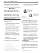
11.2.1 Burner
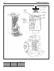
Check the burner for debris. Remove the blower
arm assembly to access the burner. Remove the 4 bolts
connecting the blower to the arm (see Figure 32).
Remove the 5 bolts, which hold the burner arm in place.
Pull burner up and out. Clean burner, if necessary, by
blowing compressed air from the outside of the burner
into the center of the burner, and wipe the inside of the
burner clean with glass cleaner. A dirty burner may be an
indication of improper combustion or dirty combustion
air. Determine the cause, and correct. If damaged,
replace the burner gasket when replacing the burner.
NOTE: When installing the burner, make sure the ange
is aligned with the mating surface, as each is keyed to
control t.
11.2.2 Appliance Control
Mascot II has an integrated control that
incorporates manual reset high limit control, operating
temperature control, modulating control, ignition
control, outdoor reset control, pump control and many
other features. If any of these features are thought
to be defective, please consult the factory for proper
trouble shooting practices prior to replacing the control.
If control replacement is required, turn off all power
to the appliance and shut off all manual gas valves to
the appliance. Remove the front door to the appliance
and the control panel plastic bezel. Remove all wire
connections from the control board. The control board
connections are keyed to only allow connection in the
proper location, but proper handling techniques should
be used to avoid damage to the wiring or connectors. To
remove the control push in on the two tabs on the left
side of the board to unlatch the clips from the control
panel. Rotate the control around the fastening points
on the right side of the control to remove the hooks
from the control panel. To replace the control repeat the
steps above in the reverse order making sure to connect
all wires in the proper location. Place the appliance in
operation following the steps outlined in Section 10.
11.2.3 Ignitor Assembly
The ignitor assembly is a two rod system that
consists of a ground rod and a sense rod. To remove the
ignitor assembly, shut off the 120 Volt power supply to
the appliance. Turn off all manual gas valves connecting
the appliance to the main gas supply line. Remove the
front door of the boiler to gain access to the ignitor
assembly. Remove the two wires connected to the
assembly. Then remove the two bolts connecting the
ignitor assembly to the burner door. Remove and replace
the old ignitor assembly gasket. Reinstall a new ignitor
assembly in the reverse order if the old assembly is
determined defective. Replace gasket if necessary.