
Install and Operating Manual User guide

LAARS Heating Systems
Page 34
11.2.4 Flame Sensor
The ame sensor is a single rod system. To replace
the ame sensor electrode, shut off the 120 Volt power
supply to the boiler. Turn off all manual gas valves
connecting the boiler to the main gas supply line.
Remove the front door of the boiler to gain access to the
ame sensor electrode. Remove the ame sensor wire
from the electrode. Remove the two bolts fastening the
electrode to the burner doors. Remove and replace the
old ame sensor gasket. Reinstall a new ame sensor
electrode in the reverse order if the old electrode is
determined defective.
Caution
Igniters and sensors get hot and
can cause burns or injury.
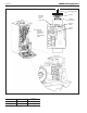
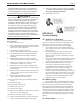
11.2.5 Blower
The combustion air blower is a high-pressure
centrifugal blower with a variable speed motor. Speed
of the motor is determined by the control logic. 120
Volts remain on to the blower at all times. If a blower
change is required, turn off the 120 Volt power and gas
supply to the unit. Take the front panel off. Disconnect
the 120 Volt and control signal connections from the
blower. Disconnect the bolts connecting the venturi to
the blower housing. Disconnect the fan outlet bolts from
the burner door blower arm. If the fan is determined
to be defective replace the existing fan with a new one
reversing the steps above. Make sure to install all of the
required O-rings and gaskets between the blower arm
and the blower and blower face and venturi ange.
11.2.6 Heat Exchanger Coils
Black carbon soot buildup on the external surfaces
of the heat exchanger is caused by one or more of the
following; incomplete combustion, combustion air
problems, venting problems and heater short cycling.
Soot buildup or other debris on the heat exchanger may
restrict the ue passages.
If black carbon soot buildup on the heat exchanger
is suspected, disconnect electrical supply to the unit,
and turn off the gas supply by closing the manual gas
valve on the unit. Access the heat exchanger through
the burner door at the front of the boiler, and inspect the
tubing using a ashlight. If there is a buildup of black
carbon soot or other debris on the heat exchanger, clean
per the following:
Caution
Black carbon soot buildup on a dirty heat exchanger
can be ignited by a random spark or ame. To prevent
this from happening, dampen the soot deposits with
a wet brush or ne water spray before servicing the
heat exchanger.
1. Shut off the 120 Volt power supply to the boiler
2. Turn off all manual gas valves connecting the
boiler to the main gas supply line.
3. Remove the four bolts connecting the blower
ange to the burner door arm.
4. Remove the nuts located on the outside diameter of
the burner door to the heat exchanger.
5. Remove the burner door/burner assembly from the
heat exchanger.
6. Disconnect the condensate drain line.
7. Attach a longer hose to drain and run to a bucket.
8. Clean the heat exchanger by brushing light
accumulations of soot and debris. Use a brush
with soft bristle (non metal) to avoid damaging the
surface of the heat exchanger tubes.
9. Once the tubes have been brushed clean rinse
the tubes and combustion chamber with a small
amount of water to rinse all of the debris out of
the bottom of the ue collector and into the longer
condensate trap line, which is being diverted into a
separate container.
NOTE: The Warranty does not cover damage caused
by lack of required maintenance, lack of water ow,
or improper operating practices.
WARNING
Failure to rinse the debris from the heat exchanger
and temporary drain line may lead to clogged
condensate lines, traps and neutralizers. Condensate
pumps (if used) may also be damaged from the
debris left behind, possibly causing property damage.
11. Install all components removed in
the reverse order to place the appliance back in
operation. Make sure all gaskets are in place as
components are installed. Replace any damaged
gaskets. Do NOT reuse damaged gaskets.
12. Place the appliance in operation according to
Section 10 checking all gas connections for leaks.
Conrm all fasteners are tight.
11.2.7 Gas Conversion
Mascot II units can be converted from natural
to propane gas or from propane to natural gas easily
in the eld. If a gas conversion is performed, the unit
must be identied with the appropriate gas labels and
a conversion sticker to allow technicians performing
maintenance in the future to properly identify the gas
type of the appliance. These stickers are included with
the boiler during shipment.
WARNING
This conversion shall be installed by a qualied
service agency in accordance with the manufacturer's
instructions and all applicable codes and
requirements of the authority having jurisdiction. If
the information in these instructions is not followed
exactly, a re, an explosion or production of carbon
monoxide may result causing property damage,
personal injury or loss of life. The qualied
service agency is responsible for the proper and