
Install and Operating Manual Owner's manual

Installation and Operation Instructions Document 4206
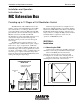
The MC Extension Box (MCX) increases the
number of stages a Laars Modulating Control (MC)
can control from 4 to 12. All logic, memory, and
control algorithms reside in the MC panel. The MC
panel directly controls four built-in stages. When an
MCX is connected to the MC, the MC will
automatically recognize eight additional stages. Any
of the twelve stages can be the lead stage and
automatic rotation provides even wear among all
active stages.
The MCX can be equipped with up to four
output cards, each of which controls a pair of stages.
There are two types of output cards: 135Ω cards
control up to two fully modulating 135Ω stages, and
Current/Voltage cards can be programmed to control
two 0-5V, 1-5V, 0-10V, 2-10V, or 4-20mA stages. To
select the type of output for Current/Voltage cards,
follow the directions in the MC I/O Manual (System
Startup, Selecting the Output Type).
Installation and Operation
Instructions for
MC Extension Box
Providing up to 12 Stages of Full Modulation Control
Each new stage must also be configured for its
Mode (Auto, Manual, Standby, On, and Off), Ignition
Start Point, and Modulation Start Point as described in
the MC I/O manual (Stage Settings). All other steps
and procedures to configure the MC presented in its I/
O manual must be completed to insure smooth
operation of a MC/MCX system.
SECTION 1.
Installation
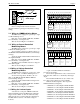
1.1 Mounting the EXM
Select a location adjacent to the MC control and
within the reach of the provided Panel-to-Panel cable.
Remove the MCX panel from the metal
enclosure by removing the top center screw and
loosening the two bottom screws. Lift the panel out.
Screw the enclosure to the surface through the
mounting holes in the back of the enclosure.
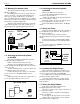
J12
Card 4 Card 3 Card 2
Card 1
EXTENSION MODULE
REAR VIEW
Fuse
Connection to
MC
Mount Output
Card 4 here to
control Stages
K and L
Output Cards are ordered
separately as required
Mount Output
Card 3 here to
control Stages
IandJ
Mount Output
Card 2 here to
control Stages
GandH
Mount Output
Card here to
control Stages
EandF
Mounting Holes
Figure 1. MCX Rear View.
Figure 2. Mounting Holes.