
Install Instructions
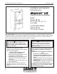


LAARS Heating Systems
PR
15, July 22nd 2014
TABLE OF CONTENTS
SECTION 1.
General Information
1.1 Introduction ........................................................ 1
1.2 To Open the Mascot LX ...................................... 1
1.3 Rating Plate ........................................................ 1
1.4 Model Nomenclature........................................... 1
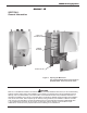
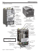
1.5 Mascot LX Overview ........................................... 2
1.6 Start Up / Shut Down Instruction (Decal) ............ 3
1.7 Dimensions for all Sizes ..................................... 4
1.8 Unpacking ........................................................... 6
1.9 Warranty ............................................................. 6
SECTION 2.
Locating the Appliance
2.1 Locating the Appliance........................................ 7
2.2 Correct Vent Distance
from Outside Wall or Roof Termination ............... 7
2.1 Wall Mount Hole Locations ................................. 8
SECTION 3.
Venting and Combustion Air
3.1 Combustion Air ................................................... 9
3.1.1 Combustion Air from Room................................. 9
3.1.2 Ducted Combustion Air ..................................... 10
3.2 Venting (Exhaust) ............................................. 10
3.2.1 About Common Venting .................................... 12
3.3 Locating Vent & Combustion Vent Terminals .... 13
3.3.1 Side Wall Vent Terminal .................................... 13
3.3.2 Side Wall Combustion Air Terminal ................... 13
3.3.3 Vertical Vent Terminal ....................................... 15
3.3.4 Vertical Combustion Air Terminal ...................... 15
3.3.5 Installations in the Commonwealth
of Massachusetts .............................................. 15
3.4 Common Vent Test ........................................... 16
SECTION 4.
Gas Supply and Piping
4.1 Gas Supply and Piping .......................................... 17
SECTION 5.
Pump Capacity
5.1 Mascot LX Heating System Pump Capacity .......... 18
SECTION 6.
Water Connections
6.1 Central Heat System Piping.............................. 19
6.2 Cold Water Make-Up ........................................ 19
6.3 Freeze Protection ............................................. 19
6.4 Recognized Chemicals ..................................... 20
6.5 Domestic Hot Water Piping (DHW and MLXC) . 20
6.6 Indirect Water Heater Piping ............................. 20
6.7 Condensate Drain ............................................. 20
6.8 Piping Schematics .......................................21-26
SECTION 7.
Electrical Connections
7.1 Main Power ....................................................... 27
7.2 Pump Connections ........................................... 27
7.3 24Vac Transformer Circuit Breaker ................... 27
7.4 Central Heat - Call for Heat .............................. 27
7.5 Outdoor Air Temperature Sensor ...................... 27
7.6 Domestic Hot Water Connection ...................... 27
7.7 System Sensor
(lead lag/cascading operation only) .................. 27
7.8 External Control Connections ........................... 27
7.9 Ladder Diagram, Connections, and
Wiring Diagrams ..........................................28-30