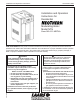
Installation and Operation Instructions Document 1252D Installation and Operation Instructions for Residential ® Modulating Boiler Model NTH Sizes 080–210 MBTU/h FOR YOUR SAFETY: This product must be installed and serviced by a professional service technician, qualified in hot water boiler and heater installation and maintenance. Improper installation and/or operation could create carbon monoxide gas in flue gases which could cause serious injury, property damage, or death.
LAARS Heating Systems Table of Contents Section 1 General Information 1.1 1.2 1.3 1.4 1.5 1.6 Section 6 Water Connections Introduction........................................................ 1 Model Identification (Nomenclature).................. 1 Appliance Overview........................................... 2 Warranty............................................................ 3 Unpacking.......................................................... 3 Dimensions............................................
NEOTHERM Residential Boilers Section 9 First Start-up and Adjustment Instructions 9.1 9.2 9.3 9.4 Filling the Boiler System.................................. 46 First Operation................................................. 46 Restarting the NeoTherm Unit......................... 47 Shutting Down the NeoTherm Unit.................. 47 Section 10 Maintenance 10.1 10.2 10.3 System Maintenance....................................... 48 Appliance Maintenance and Component Description.......................
LAARS Heating Systems
Page 1 NEOTHERM Residential Boilers Section 1 GENERAL INFORMATION WARNING NeoTherm units must be installed in accordance with the procedures detailed in this manual, or the LAARS Heating Systems warranty will be voided. The installation must conform to the requirements of the local jurisdiction having authority, and, in the United States, to the latest edition of the National Fuel Gas Code, ANSI Z223.1/NFPA54. In Canada, the installation must conform to the latest edition of CSA B149.
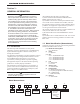
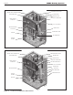
Page 2 LAARS Heating Systems EXHAUST VENT CONNECTION PRESSURE RELIEF VALVE GAS CONNECTION WATER INLET WATER OUTLET USER CONTROL INTERFACE AIR INLET CONNECTION ON / OFF SWITCH HEAT EXCHANGER DRAIN VALVE GAS VALVE CONDENSATE TRAP VENTURI AIR TRANSITION AIR/ GAS BLOWER Figure 1.
Page 3 NEOTHERM Residential Boilers 1.4 Warranty LAARS Heating Systems NeoTherm appliances are covered by a limited warranty. The owner should complete the warranty registration at www.Laars.com. All warranty claims must be made to an authorized LAARS Heating Systems representative. Claims must include the serial number and model (this information can be found on the rating plate), installation date, and name of the installer. Shipping costs are not included in the warranty coverage.
Page 4 LAARS Heating Systems 1.
Page 5 NEOTHERM Residential Boilers Section 2 LOCATING THE APPLIANCE 2.1 General Information The NeoTherm unit is designed for indoor installations only. The appliance should be located to provide clearances on all sides for maintenance and inspection. It should not be located in an area where leakage of any connections will result in damage to the area adjacent to the appliance or to lower floors of the structure.
Page 6 LAARS Heating Systems Section 3 VENTING AND COMBUSTION AIR 3.1 General Venting This product requires a special venting system. Refer to venting supplier’s instructions for complete parts list and method of installation. The manufacturers and product lines listed on the following tables have been tested and authorized to safely operate with Laars equipment.
Page 7 NEOTHERM Residential Boilers Combustion Air From Room not be less than the sum of the areas of all vent connectors in the confined space. In the United States, the most common requirements specify that the space shall communicate with the outdoors in accordance with method 1 or 2, which follow. Where ducts are used, they shall be of the same cross-sectional area as the free area of the openings to which they connect.
Page 8 LAARS Heating Systems 3.3 Venting WARNING Failure to use polypropylene CPVC or stainless steel venting for the first 30” of vent material or for any part of the venting that is installed inside a closet may lead to property damage, personal injury or death. The proper length of this material is supplied with boiler. Boilers in the U.S. may use pipe included with the boiler.
Page 9 NEOTHERM Residential Boilers E. CPVC exhaust pipe section (80-210) (not incl.) F. outdoor/system sensor kit G. flow switch kit (399-850MBH, Commercial Only) H. alternate size vent/terminal screens J. exhaust vent adapter CPVC/ST ST (750-850) * * * * It is the responsibility of the appropriately licensed technician installing this NeoTherm unit to use ULC S636 certified vent material consistent with the requirements as described in the Venting and Combustion Air section.
Page 10 LAARS Heating Systems 3.4 Locating Vent and Combustion Air Terminals (continued) 1. Figure 6 shows the requirements for mechanical vent terminal clearances for the U.S. and Canada. 2. Vent terminals for condensing appliances or appliances with condensing vents are not permitted to terminate above a public walkway, or over an area where condensate or vapor could create a nuisance or hazard. 3. Locate the vent terminal so that vent gases cannot be drawn into air conditioning system inlets. 4.
Page 11 NEOTHERM Residential Boilers U.S. Installations (see note 1) Canadian Installations (see note 2) A= Clearance above grade, veranda, porch, deck, or balcony 12 inches (30 cm) See note 6 12 inches (30 cm) See note 6 B= Clearance to window or door that may be opened Direct vent only: 12 inches (30cm); Other than Direct vent: 4 ft (1.
Page 12 LAARS Heating Systems 3.4 Locating Vent and Combustion Air Terminals (continued) 720 and be ANSI/UL 2034 listed and IAS certified. 3. Signage A metal or plastic identification plate shall be permanently mounted to the exterior of the building at a minimum height of eight (8) feet above grade directly in line with the exhaust vent terminal for horizontally vented gas fueled heating appliance or equipment.
Page 13 NEOTHERM Residential Boilers At the time of removal of an existing boiler, the following steps shall be followed with each appliance remaining connected to the common venting system placed in operation, while the other appliances remaining connected to the common venting system are not in operation. 1. Seal any unused openings in the common venting system. 2.
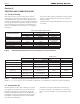
Page 14 LAARS Heating Systems NEOTHERM NATURAL GAS REQUIRED SIZE CU FT / HR. 80 105 150 80 105 150 210 210 Section 5 PUMP REQUIREMENTS TO SIZE PIPING: Measure linear distance from meter outlet to last boiler. Add total input of all boilers and divide by 1000 to obtain cu ft / hr required. Add total equivalent length of fittings used according to Table 6B. Align total length (pipe and fittings) on left side column of Table 6C with highest cubic feet of gas required. Table 10.
Page 15 NEOTHERM Residential Boilers Section 6 WATER CONNECTIONS NTH BOILER 6.1 NTH System Piping - Hot Supply Connections NOTE: This appliance must be installed in a closed pressure system with a minimum of 12 psi (82.7kPa) static pressure at the boiler. Hot water piping should be supported by suitable hangers or floor stands. Do not support piping with this appliance. Due to expansion and contraction of copper pipe, consideration should be given to the type of hangers used.
Page 16 LAARS Heating Systems 6.3 Condensate Drain A condensate drain trap is built into the NeoTherm unit. Connect a 3/4” PVC pipe between the drain connection and a floor drain (or a condensate pump if a floor drain is not accessible). The condensate drain must be installed so as to prevent accumulation of condensate. When a condensate pump is not used, the tubing must continuously slope downward toward the drain with no spiraling. Consult local codes for the proper disposal method for the condensate.
NEOTHERM Residential Boilers Figure 9.
Page 18 LAARS Heating Systems Figure 10.
NEOTHERM Residential Boilers Figure 11.
Page 20 LAARS Heating Systems Figure 12.
NEOTHERM Residential Boilers Page 21 Figure 13.
Page 22 LAARS Heating Systems Figure 14. - Hydronic Piping — Heating Zones with Indirect DHW Tank Piped with Zone Pumps The indirect DHW tank is piped directly off of the boiler. The boiler pump must shut down during DHW operation.
NEOTHERM Residential Boilers Figure 15. - Hydronic Piping, Multiple Boilers with Indirect DHW Off of One Boiler The boiler pump must shut down during DHW operation.
Page 24 LAARS Heating Systems Section 7 ELECTRICAL AND WIRING DIAGRAMS 7.1 Installation Warnings WARNING The appliance must be electrically grounded in accordance with the requirements of the authority having jurisdiction or, in the absence of such requirements, with the latest edition of the National Electrical Code, ANSI/NFPA 70, in the U.S. and with the latest edition of CSA C22.1 Canadian Electrical Code, Part 1, in Canada.
Page 25 NEOTHERM Residential Boilers Figure 16. - Control Panel Layout 7.4 Hydronic Heating Using External Modulation Control About External Control When the NeoTherm is used for hydronic heating with external modulation control, a call for heat must be supplied to the “T-T or Interlock” terminal. Once the call is supplied the control starts the Boiler and System pumps and begins the ignition process. Once in Run, the NeoTherm monitors the flame signal, call for heat, safeties, and water temperatures.
Page 26 7.6 LAARS Heating Systems Lead Lag Connections NeoTherm boilers can be connected in a lead / lag series up to a total of 8 residential NeoTherms. One as the Lead control and 7 more as the following controllers. For general info and menu set-up for Lead Lag using your NeoTherm Touchscreen, See page 41 ‘About Lead Lag’. Figure 17.
Page 27 NEOTHERM Residential Boilers NeoTherm residential boilers can be controlled and monitored using the Laars Gateway system, but only if one of the EMEA User Interfaces is replaced with the Laars color touchscreen. Call your Laars Representative for the touchscreen kit Following Boiler Optional Touchscreen User Interface Kit (KM50D7130) and the Laars Gateway Control (H2354400, Doc# 4236).
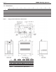
Page 28 7.8 LAARS Heating Systems System Wiring Diagram LTGN OR/GN DISPLAY DISPLAY Y (Honeywell) TB4 24V COMMON 1 OR/WH NC PRESSURE COM SWITCH BR Y Y Y TO TB1 PIN2 BLK Y 2 TRANSFORMER 110VAC INPUT 24VAC OUTPUT Y 8 6 4 2 X07 7 5 3 1 12 10 8 6 4 2 X01 11 9 7 5 3 1 TO GAS VALVE P1 TO J4-10 WH TO TB2 PIN2 OPTIONAL SWITCH USED ON SOME MODELS. IF SWITCH IS NOT INSTALLED IN THIS LOCATION.
Page 29 NEOTHERM Residential Boilers LTGN Y OR/GN DISPLAY (Honeywell) 8 6 4 2 X07 7 5 3 1 12 10 8 6 4 2 X01 11 9 7 5 3 1 PRESSURE SWITCH Y OR/GN OR/BLK BA VDC B A V- MB2 V+ MB1 R DKB/Y DKB/Y MS-2 1 2 3 4 R2 GY VT WH/GY WH/OR DKB DKB/Y DKB J5-1 J5-2 J9-6 J9-5 J9-4 CUSTOMER POWER INPUT GND 1 WH OR TN/R TO TB6 P2 TO TB6 P1 SYS PUMP OR TN/BRN DHW OR DKB PUMP GND SW 1 L NEUTRAL L 6 TN/BLK 2 NEUTRAL TN/BL CONTROL MODULE CONTROL MODULE (Honeywell) DKB R1 OR CR
Page 30 7.9 LAARS Heating Systems Ladder Diagram Figure 19.
Page 31 NEOTHERM Residential Boilers Section 8 THE USER INTERFACE 8.1 About the User Interface 8.2 The User Interface of the NeoTherm has two main parts: Navigating into the Display area menus is as easy as it looks. The Info/Install button will be the primary button that you will use to start, and the OK button is what you press to select and approve the parameters that you have set on the Display. The arrow keys are for moving up and down, left and right within the menus.
Page 32 LAARS Heating Systems The Neotherm ‘User Interface’ was updated for the 2013 model year to the EMEA display shown in Figure 27. For older NeoTherms with the white user inerface, you will need to download the 1218G-NH.pdf from the ‘Discontinued Documents’ on Laars.com. • The lower section shows any current lockouts, holds, or alerts. 8.
Page 33 NEOTHERM Residential Boilers Quick Start This menu gives you an easy way to check or change the most common settings on the unit: • CH setpoint • DHW setpoint • Outdoor reset • Low water temperature • Maximum outdoor temperature • Minimum outdoor temperature • Adjustable high limit • Adjustable low limit See Section 8B for more information. Login If you want to change a setup value or function, and the system requires a password, you can enter it here. See the section on “Login Display.
Page 34 • The current setting appears in the upper right-hand corner of the screen. In this example, this is 1 minute. • The numbers near the left edge of the screen show the allowable range for this value. In this case, the time can be set anywhere between 0 seconds (function turned off) and 15 hours. In this example we will change the time delay to 5 minutes. • Press the Left- and Right-Arrow buttons to move to the box you want. In this case, we want to change the middle box - the box for Minutes.
Page 35 NEOTHERM Residential Boilers 8.6 Quick Start Changing a Value Using a “Slider” There is another type of control screen you may see. This type of screen uses a “slider” to set the value. This system is used on the LCD Contrast screen (available under Display Setup.) See Fig. 33. Figure 28. - Quick Start Menu Changing the CH (Central Heat) Setpoint Figure 26. – Changing LCD Contrast • Use the Left- and Right-Arrow buttons to move the bar and adjust the contrast.
Page 36 Outdoor Reset Functions The next four lines in the display are used to set up the Outdoor Reset functions: • Outdoor Reset Enable/Disable - Note: This function can be Enabled/Disabled only by a factory trained technician. • Low Water Temperature - Use the Up- and DownButtons to select the function, use Up- and Down- to select the new value, then press the round OK button.
Page 37 NEOTHERM Residential Boilers Figure 31. - Control Panel Layout Connect the outdoor air temperature sensor to terminal block 7 (TB7), using the connections labeled Outdoor Temp Sensor. 8.11 Outdoor Reset About Outdoor Reset The Outdoor Reset feature calculates a correction for the hydronic (Central Heat) setpoint depending on the outdoor temperature. This allows the system to compensate for changes in the outdoor temperature and run more efficiently.
Page 38 LAARS Heating Systems Here are instructions for setting up the Outdoor Reset function. Notice that these instructions will be different, depending on whether you have a single boiler or more than one boiler (using Lead Lag operation). using the Lead/ Lag function – How to get there: From the “Home” screen, press “I” to go to “Info/ Install.” Choose “Advanced Setup,” then go to “Lead/ Lag Configuration.” Select “Lead/ Lag Outdoor Reset.” Set the value on the line for “Min. Outdoor Temp.
Page 39 NEOTHERM Residential Boilers 8.13 be used for both functions.) Here are instructions for setting up the Warm Weather Shutdown function. Notice that these instructions will be different, depending on whether your system has a single boiler or more than one boiler (using Lead Lag operation).
Page 40 The DHW priority demand forces the control to operate to the DHW setpoint, de-energizes the System pump and energizes the DHW pump. The domestic hot water temperature sensor or an aquastat is used to monitor the DHW demand. The control uses the DHW sensor to control the operation and modulation rate of the appliance when there is a DHW demand. Hydronic Heating Using Local Lead-Lag/Cascading Feature with Indirect Hot Water (For a complete explanation of the Lead Lag system, see Section 8.14.
Page 41 NEOTHERM Residential Boilers 2. Set the setpoint for the DHW function. If your system has just one boiler – How to get there: From the “Home” screen, press “I” to go to “Info/ Install.” Choose “Advanced Setup,” then go to “DHW Configuration.” Select “DHW Setpoint.” If your system has more than one boiler, and is controlled using the Lead/ Lag function – How to get there: On the unit used as the Lead Lag Master, from the “Home” screen, press “I” to go to “Info/ Install.
Page 42 8.14 LAARS Heating Systems About Lead Lag Operation (continued) Boiler 1 Boiler 2 Boiler 3 Boiler 4 Display Controller Burner Figure 33. – “Lead Lag” Operation in a System with Four Boilers. Note - the Displays on Boilers 2 thru 4 will display information pertaining only to that specific boiler. NOTE: If your NeoTherms are Lead Lag configured, you will find it very useful to customize your Home Display to show LL Operating Temp and LL Setpoint Temp. Please refer to Section 8.
Page 43 NEOTHERM Residential Boilers Low demand The first boiler in sequence fires at less than 65% Low demand The first boiler in sequence fires at less than 65% First boiler Second boiler Third boiler First boiler Second boiler Third boiler Demand increases Once the first boiler reaches 65%, the second boiler switches on, and both modulate together between 25% and 65% (this adjustable up to 25% and 85%) Demand increases Once the first boiler reaches 65%, the second boiler switches on, and both m
Page 44 8.14 LAARS Heating Systems bout Lead Lag Operation A (continued) 8.15 Adjusting CO2 1. Measure the CO2/O2 in the flue products at high fire. The NeoTherm can be forced to high fire to allow for easier setup. The controller has a feature that makes it easy to go directly to the high fire condition. The unit will operate at high fire for 5 minutes, then modulate down automatically. How to get there: From the “Home” screen, press “I” to go to “Info/ Install.
Page 45 NEOTHERM Residential Boilers The Gas Valve in the 80 thru 210 is at the front of the unit and can be reached after the front panel is pulled forward and then off. Always be patient with your combustion analyzer when making adjustments to the valve at both Hi-Fire and Low-Fire. Be sure to put the cap back onto the valve when you are done making your adjustments at the gas valve. Gas Pressure Tap under cap Figure 36.
Page 46 Section 9 FIRST START-UP AND ADJUSTMENT INSTRUCTIONS 9.1 Filling the Boiler System 1. If a make-up water pump is employed, adjust the pressure switch on the pumping system to provide a minimum of 12 psi (81.8 kPa) at the highest point in the heating loop. 3. If a water pressure regulator is provided on the make-up water line, adjust the pressure regulator to provide at least 12 psi (81.8 kPa) at the highest point in the heating loop. 4.
Page 47 NEOTHERM Residential Boilers and turn on the gas and main electrical power (circuit breaker) to the unit. 4. Turn the NeoTherm on at the On/Off switch. 5. The NeoTherm unit will begin the start sequence. The blower and pump will energize for the pre-purge period, then the ignition sequence will start. After all safety devices have been verified, the gas valve will open. If ignition doesn’t occur, turn off the NeoTherm, and check that there is proper gas supply. Wait 5 minutes before restarting.
Page 48 Section 10 MAINTENANCE WARNING Disconnect all power to the appliance before attempting any service. Contact with electricity can result in severe injury or death. 10.1 System Maintenance Do this once a year, unless otherwise noted. 1. Lubricate the system water-circulating pump, if required, per the instructions on the pump. 2. If a strainer is employed in a pressure reducing valve or the piping, clean it every six months. 3.
Page 49 NEOTHERM Residential Boilers factory for proper trouble shooting practices prior to replacing the control. If control replacement is required, turn off all power to the appliance and shut off all manual gas valves to the appliance. Remove the front door to the appliance and the plastic bezel and the control panel. Remove all wire connections from the control board.
Page 50 Transformer with Integral Circuit Breaker The appliance has a 24Vac transformer with integral 4 amp circuit breaker installed to supply the control voltage required for the appliance. The transformer is sized to provide power for the NeoTherm unit only, and should not be used to supply power to additional field devices. If additional loads are added, or a short occurs during installation, the integral circuit breaker may trip.
Page 51 NEOTHERM Residential Boilers Optional Pressure Gas Switches size (mbtu) Kit number The high and low pressure gas switches are 24V manual reset switches that act to cut power to the gas valves if the gas pressure is too low or too high for proper operation. 80 CA006201 105 CA006202 150 CA006203 If your boiler is equipped with the Optional pressure gas switches, then the Low Pressure Switch will need to be reset. 210 CA006204 Table 21.
Page 52 Section 11 OPERATING DETAILS AND TROUBLESHOOTING 11.1 LAARS Heating Systems 5. There is a pre-ignition time of two seconds to check the flame sensor operation and status. During this period an intermittent spark can be seen. 6. Next there is a trial for ignition period of four seconds. The direct spark ignition switches to constant spark for three seconds. During this time the gas valve is open.
Page 53 NEOTHERM Residential Boilers 11.5 Anti-Short-Cycle (ASC) Because the NeoTherm unit is a modulating boiler, and its input will decrease when there is a reduction in the heating load, short cycling is greatly reduced. If the heating load drops below the minimum input of the boiler for an extended period, the boiler will have a tendency to short cycle. This can be a symptom of improper control strategy or setpoints, or a load distribution problem.
Page 54 LAARS Heating Systems Section 12 REPLACEMENT PARTS Use only genuine LAARS replacement parts. 12.1 General Information To order or purchase parts for the LAARS NeoTherm, contact your nearest LAARS dealer or distributor. If they cannot supply you with what you need, contact Customer Service. (See the back cover for the address, telephone and fax numbers.) 12.
Page 55 NEOTHERM Residential Boilers SIZE ITEM DESCRIPTION 80 SIZE 105 SIZE 150 SIZE 210 25 Mounting Rail R15D1004 R15D1004 R15D1004 R30D1004 27 Condensate Trap Assy R20D4020 R20D4020 R20D4020 R20D4020 28 Heat Exch. Rail Clip R50D1006 (2) R50D1006 — — (2) 30 PVC Reducer — — RP2053000 RP2053000 30a CPVC Reducer or Coupling RD2010501 RD2010501 RP2065600 RP2065600 30b 2” Dia.
Page 56 LAARS Heating Systems SIZE SIZE SIZE SIZE ITEM DESCRIPTION 80 105 150 210 74B Screw, Ignitor/ Flame Sensor m4-.7X8mm S2112700 m4-.7X8mm S2112700 m4-.7X8mm S2112700 m4-.
NEOTHERM Residential Boilers Page 57 Optional Touchscreen User Interface Kit (KM50D7130) Call Factory. Figure 40.
Page 58 LAARS Heating Systems Figure 41. - Gas Train Components, Sizes 80-210 S2111000 Figure 42.
Page 59 NEOTHERM Residential Boilers 66 63 64 67 65 60 68A Figure 43.
Page 60 Figure 44.
Page 61 NEOTHERM Residential Boilers Appendix A SOFTWARE CONTROL FUNCTIONS This table includes a listing of all of the control functions that can be used by the operator or installer. Functions that require a password are indicated in the second column. Name PW? Function How to get there Adjustable high limit Y The absolute high limit for the water outlet is pre-set at the factory. If desired, you can set a lower value here.
Page 62 LAARS Heating Systems Name PW? Function How to get there Demand switch (CH) - Set to “STAT terminal.” Info/ Advanced Setup/ CH Configuration DHW pump control Y The boiler pump can be turned on manually, or it can be set to operate automatically. Info/ Test/ Manual Pump Operation A new value can be written here if the pump or controller is replaced. Info/ Advanced Setup/ System Config./ Statistics Config.
Page 63 NEOTHERM Residential Boilers Name PW? Max. outdoor temp. (CH) - Max. outdoor temp. (LL) - Function How to get there Used with Outdoor Reset – Quick Start This is the maximum outdoor temperature at which the Outdoor Reset feature will be active. Above this point, the Low Water Temp. will be used as the setpoint. Info/ Advanced Setup/ CH Configuration/ Outdoor Reset Config.
Page 64 LAARS Heating Systems Name PW? Function How to get there Off hysteresis (DHW) - When producing Domestic Hot Water – Info/ Advanced Setup/ DHW Configuration The control system will not shut off the boiler until the temperature at the System sensor rises to the DHW setpoint plus a hysteresis value (normally about 10°F). Off hysteresis (LL) - When using the Lead/ Lag system to control multiple boilers – Info/ Advanced Setup/ Lead Lag Configuration/ LL Master Config.
Page 65 NEOTHERM Residential Boilers Name PW? Function How to get there Pump exercise interval Y The system can be set to exercise the pumps at set intervals. Enter a non-zero value to turn on the function. Info/ Advanced Setup/ System Config./ Pump Config. Pump exercise time Y If the pump exercise feature is enabled, this value sets the length of time that each pump will be exercised. Info/ Advanced Setup/ System Config./ Pump Config.
Page 66 LAARS Heating Systems Appendix B ERROR MESSAGES This table includes a listing of the faults that might be generated by the controller, and displayed on the Operator Interface. Some of these can be corrected by an installer changing a parameter, while other conditions are more complicated, and will require a service technician. The first column lists the code number that will appear at the beginning of the Lockout or Hold message. The second column lists a short description of the condition.
Page 67 NEOTHERM Residential Boilers 17 Internal fault: L Safety relay test failed due to safety relay not OFF 18 Internal fault: L Safety relay test failed due to feedback not ON 19 Internal fault: Internal fault 1. Reset module 2. If fault repeats, replace module.
Page 68 53 LAARS Heating Systems AC input phases reversed L 1. Check the module and display connections. 2. Check the module power supply and make sure that both frequency and voltage meet the specifications. 3. On 24 VAC applications, assure that J4 terminal 10 and J8 terminal 2 are connected together. 59 Internal Fault: Mux pin shorted L Internal Fault. 1. Reset module. 2. If fault repeats, replace module. 61 Anti short cycle H Will not be a lockout fault. Hold Only.
Page 69 NEOTHERM Residential Boilers 80 DHW (Domestic Hot Water) high limit H or L 1. Check wiring and correct any possible errors. 2. Replace the DHW high limit. 3. If previous steps are correct and fault persists, replace the module. 81 Delta T limit H or L 1. Check inlet and outlet sensors and pump circuits for proper operation. 2. Recheck the Delta T Limit to confirm proper setting. 3. If previous steps are correct and fault persists, replace the module. 82 Stack limit H or L 1.
Page 70 105 LAARS Heating Systems Flame detected out of sequence H or L 1. Check that flame is not present in the combustion chamber. Correct any errors. 2. Make sure that the flame detector is wired to the correct terminal. 3. Make sure the F & G wires are protected from stray noise pickup. 4. Reset and sequence the module. If code reappears, replace the flame detector. 5. Reset and sequence the module. If code reappears, replace the module. 106 Flame lost in MFEP L 1.
Page 71 NEOTHERM Residential Boilers 156 Combustion pressure and flame On H or L 1. Check that flame is not present in the combustion chamber. Correct any errors. 2. Make sure that the flame detector is wired to the correct terminal. 3. Make sure the F & G wires are protected from stray noise pickup. 157 Combustion pressure and flame Off L 4. Reset and sequence the module, if code reappears, replace the flame detector. 5. Reset and sequence the module, if code reappears, replace the module.
Page 72 LAARS Heating Systems 184 Invalid Blower/ HSI output setting L 185 Invalid Delta T limit enable setting L 186 Invalid Delta T limit response setting L 187 Invalid DHW (Domestic Hot Water) high limit enable setting L 188 Invalid DHW (Domestic Hot Water) high limit response setting L 189 Invalid flame sensor type setting L 2. If fault repeats, verify electrical grounding. 192 Invalid igniter on during setting L 3. If fault repeats, replace module.
Page 73 NEOTHERM Residential Boilers 205 Invalid Outlet high limit response setting L 207 Invalid PII (Pre-Ignition Interlock) enable setting L 210 Invalid Postpurge time setting L 211 Invalid Power up with lockout setting L 1. Recheck selected parameters, reverify and reset module. 212 Invalid Preignition time setting L 2. If fault repeats, verify electrical grounding. 213 Invalid Prepurge rate setting L 3. If fault repeats, replace module.
Page 74 Notes: LAARS Heating Systems
NEOTHERM Residential Boilers Notes: Page 75
NEOTHERM Residential Boilers Notes: All Manuals (Install & Operate, Start Up, and Service Manuals) can be downloaded at www.laars.com For LAARS Product and Service VIDEOS h t t p s : / / w w w. y o u t u b e . com/user/LaarsHeating H2355200D Dimensions and specifications subject to change without notice in accordance with our policy of continuous product improvement. Customer Service and Product Support: 800.900.9276 • Fax 800.559.