Installation and Operation Instructions Document 1252F Installation and Operation Instructions for NEOTHERM ® Modulating Boiler Model NTH Sizes 080–210 MBTU/h FOR YOUR SAFETY: This product must be installed and serviced by a professional service technician, qualified in hot water boiler and heater installation and maintenance. Improper installation and/or operation could create carbon monoxide gas in flue gases which could cause serious injury, property damage, or death.
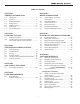
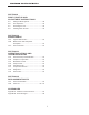
LAARS Heating Systems Table of Contents SECTION 1 GENERAL INFORMATION 1.A 1.B 1.C 1.D 1.E 1.F 1.G SECTION 6 WATER CONNECTIONS Introduction........................................................ 1 Warranty............................................................ 1 Model Identification............................................ 1 Safety Notes...................................................... 2 Model Overview................................................. 4 Dimensions............................
NEOTHERM® Residential Boilers SECTION 9 FIRST START-UP AND ADJUSTMENT INSTRUCTIONS 9.A 9.B 9.C 9.D Filling the Boiler System.................................. 48 First Operation................................................. 49 Restarting the Unit........................................... 49 Shutting Down the Unit.................................... 49 SECTION 10 MAINTENANCE 10.A 10.B 10.C System Maintenance....................................... 50 Maintenance and Component Description...........
LAARS Heating Systems
NEOTHERM® Residential Boilers SECTION 1 1.A Page 1 GENERAL INFORMATION Introduction This manual provides information necessary for the installation, operation, and maintenance of the LAARS Heating Systems NeoTherm. Read it carefully before starting the installation. NOTE: Throughout the content of this manual, the NeoTherm will be referred to as a ‘unit’. unit = NeoTherm All application and installation procedures should be reviewed completely before proceeding with the installation.
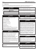
Page 2 1.A LAARS Heating Systems Safety Notes Safety Notes are used thoughout this manual to bring attention to the presence of hazards with various risk levels and to offer important information concering the life of this product. There are 3 basic types. 1 WARNING 2 CAUTION 3 Indicates an imminently hazardous situation which, if not avoided, can or will result in death or serious injury and can or will result in catastrophic property damage.
NEOTHERM® Residential Boilers WARNING Electrical Shock Hazard Electrical shock can cause severe injury, death or property damage. Disconnect the power supply before beginning installation or changing the wiring to prevent electrical shock or damage to the equipment. It may be necessary to turn off more than one power supply to disconnect. All electrical wiring is to be done in accordance with local codes, or in the absence of local codes, with: 1) The National Electrical Code ANSI/NFPA No.
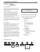
Page 4 1.B LAARS Heating Systems Model Overview EXHAUST VENT CONNECTION GAS CONNECTION PRESSURE RELIEF VALVE WATER INLET WATER OUTLET USER CONTROL INTERFACE AIR INLET CONNECTION ON / OFF SWITCH HEAT EXCHANGER GAS VALVE VENTURI DRAIN VALVE CONDENSATE TRAP AIR TRANSITION AIR/ GAS BLOWER Figure 1.
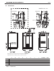
Page 5 NEOTHERM® Residential Boilers 1.C Dimensions 02'(/6 02'(/6 $ *$6 ,1/(7 $ *$6 ,1/(7 % % 21 2)) 6ZLWFK ) ) / Dimensions are nominal and are shown in inches cm Optional pump is shown only in the front view A Size in cm B in D cm 13½ 34 105 13½ 34 6 150 13¼ 34 5¼ 14 3¼ 210 20½ 52 5¼ 14 3¼ Table 1.
Page 6 1.D LAARS Heating Systems The Installation Kit 1 This residential unit is shipped in a single crate with a boxed installation kit that contains these components. (See Figure 3) 2 1. Temperature / pressure gauge kit 2. Air intake terminal 3. Exhaust vent terminal (US only) 3 4. Jumper Terminal 5. CPVC exhaust pipe section (US only) 6. Alternate size vent/terminal screens 7. Outdoor/system sensor kit Optional: 8.
Page 7 NEOTHERM® Residential Boilers SECTION 2 2.A LOCATING THE UNIT General Information This unit is designed for indoor installations only and should be located to provide clearances on all sides for maintenance and inspection. It should not be located in an area where leakage of any connections will result in damage to the area adjacent to the unit or to lower floors of the structure.
Page 8 LAARS Heating Systems SECTION 3 3.A VENTING AND COMBUSTION AIR General Venting This unit requires a special venting system. Refer to venting supplier’s instructions for complete parts list and method of installation. The vent manufacturers listed on the following tables have been tested and authorized to safely operate with this unit. Suppliers of stainless steel and polypropylene venting that are not listed on these tables are not permitted for use with this category III/ IV unit.
Page 9 NEOTHERM® Residential Boilers Combustion Air From Room Other methods of introducing combustion and ventilation air are acceptable, providing they conform to the requirements in the applicable codes listed above. In the United States, the most common requirements specify that the space shall communicate with the outdoors in accordance with method 1 or 2, which follow. Where ducts are used, they shall be of the same cross-sectional area as the free area of the openings to which they connect.
Page 10 3.C LAARS Heating Systems Venting must be produced by the same manufacturer, and have a ULC-S636 rating. WARNING Failure to use polypropylene CPVC or stainless steel venting for the first 30” of vent material or for any part of the venting that is installed inside a closet may lead to property damage, personal injury or death. The proper length of this material is supplied with boiler. Boilers in the U.S. may use pipe included with the boiler.
Page 11 NEOTHERM® Residential Boilers Class II venting systems are further classified into four temperature ratings as follows: A Up to and including 65°C B Up to and including 90°C C Up to and including 110°C, and D Up to and including 135°C NOTE: IMPORTANT! It is the responsibility of the installer to ensure that a flue gas sampling port is installed in the vent system. This flue gas sampling port must be installed near the flue connection of the unit: within 2 feet of the flue connection.
Page 12 3.E Locating Vent and Combustion Air Terminals (continued) 1. Figure 7 shows the requirements for mechanical vent terminal clearances for the U.S. and Canada. 2. Vent terminals for condensing appliances or appliances with condensing vents are not permitted to terminate above a public walkway, or over an area where condensate or vapor could create a nuisance or hazard. 3. Locate the vent terminal so that vent gases cannot be drawn into air conditioning system inlets. 4.
Page 13 NEOTHERM® Residential Boilers U.S. Installations (see note 1) Canadian Installations (see note 2) A= Clearance above grade, veranda, porch, deck, or balcony 12 inches (30 cm) See note 6 12 inches (30 cm) See note 6 B= Clearance to window or door that may be opened Direct vent only: 12 inches (30cm); Other than Direct vent: 4 ft (1.
Page 14 LAARS Heating Systems 3.E Locating Vent and Combustion Air Terminals (continued) however, that during said thirty (30) day period, a battery operated carbon monoxide detector with an alarm be installed. Installations in the Commonwealth of Massachusetts 2. In Massachusetts the following items are required if the side-wall exhaust vent termination is less than seven (7) feet above finished grade in the area of the venting, including but not limited to decks and porches.
Page 15 NEOTHERM® Residential Boilers 3.F Common Vent Test NOTE: This section does not describe a method for common venting units. It describes what must be done when a unit is removed from a common vent system. These class IV units require special vent systems and fans for common vent. See Section “3.D Common Venting” on page 11, or contact the factory if you have questions about common venting these units.
Page 16 LAARS Heating Systems SECTION 5 Unit NATURAL GAS REQUIRED SIZE CU FT / HR. 80 105 150 80 105 150 210 210 Table 9. TO SIZE PIPING: Measure linear distance from meter outlet to last boiler. Add total input of all boilers and divide by 1000 to obtain cu ft / hr required. Add total equivalent length of fittings used according to Table 10. Align total length (pipe and fittings) on left side column of Table 11 with highest cubic feet of gas required.
Page 17 NEOTHERM® Residential Boilers SECTION 6 6.A WATER CONNECTIONS oiler System Piping - Hot Supply B Connections NOTE: This unit must be installed in a closed pressure system with a minimum of 12 psi (82.7kPa) static pressure at the boiler. Hot water piping should be supported by suitable hangers or floor stands. Do not support piping with this boiler. Due to expansion and contraction of copper pipe, consideration should be given to the type of hangers used.
Page 18 6.C LAARS Heating Systems Condensate Drain A condensate drain trap is built into the unit. Connect a 3/4” PVC pipe between the drain connection and a floor drain (or a condensate pump if a floor drain is not accessible). The condensate drain must be installed so as to prevent accumulation of condensate. When a condensate pump is not used, the tubing must continuously slope downward toward the drain with no spiraling. Consult local codes for the proper disposal method for the condensate.
NEOTHERM® Residential Boilers Figure 9.
Page 20 LAARS Heating Systems Figure 10.
NEOTHERM® Residential Boilers Figure 11.
Page 22 LAARS Heating Systems Figure 12.
NEOTHERM® Residential Boilers Page 23 Figure 13.
Page 24 LAARS Heating Systems Figure 14. Hydronic Piping — Heating Zones with Indirect DHW Tank Piped with Zone Pumps The indirect DHW tank is piped directly off of the boiler.
NEOTHERM® Residential Boilers Figure 15. Hydronic Piping, Multiple Boilers with Indirect DHW Off of One Boiler The indirect DHW tank is piped directly off of the boiler.
Page 26 SECTION 7 7.A LAARS Heating Systems ELECTRICAL AND WIRING DIAGRAMS Installation Warnings WARNING This unit must be electrically grounded in accordance with the requirements of the authority having jurisdiction or, in the absence of such requirements, with the latest edition of the National Electrical Code, ANSI/NFPA 70, in the U.S. and with the latest edition of CSA C22.1 Canadian Electrical Code, Part 1, in Canada.
Page 27 NEOTHERM® Residential Boilers Figure 16. Control Panel Layout 7.D ydronic Heating Using External H Modulation Control About External Control - When this unit is used for hydronic heating with external modulation control, a call for heat must be supplied to the “T-T or Interlock” terminal. Once the call is supplied the control starts the Boiler and System pumps and begins the ignition process. Once in Run, the unit monitors the flame signal, call for heat, safeties, and water temperatures.
Page 28 7.F Lead Lag Connections These boilers can be connected in a lead / lag series up to a total of 8 residential Units. One as the Lead control and 7 more as the following controllers. For general info and menu set-up for Lead Lag using your units Touchscreen, See page 43 ‘About Lead Lag’. Figure 17.
Page 29 NEOTHERM® Residential Boilers These boilers can be controlled and monitored using a BAS (Building Automation Systems) control, but only if one of the EMEA User Interfaces is replaced with the available color touchscreen. Call your Manufacturers Representative for the touchscreen kit Following Boiler Optional Touchscreen User Interface Kit (KM50D7130) and the BAS Control (H2354400, Doc# 4236).
Page 30 LAARS Heating Systems 7.G System Wiring Diagram TO J4-10 TO GAS VALVE P1 TB4 24V COMMON 1 Y Y TO TB1 PIN2 BLK Y 2 TRANSFORMER 110VAC INPUT 24VAC OUTPUT Y OR/WH NC COM BR Y Y OPTIONAL SWITCH USED ON SOME MODELS. IF SWITCH IS NOT INSTALLED IN THIS LOCATION.
Page 31 NEOTHERM® Residential Boilers LTGN Y OR/GN DISPLAY (Honeywell) 12 10 8 6 4 2 11 9 7 5 3 1 8 6 4 2 7 5 3 1 X01 X07 PRESSURE SWITCH Y OR/GN OR/BLK BA VDC B A V- MB2 V+ MB1 MS-2 DKB/Y DKB/Y STACK TEMP (P3) DKB 1 2 3 4 GY BRN R1 PUR OR R2 GY VT CRIMP NUT GY WH/GY WH/OR DKB DKB DKB/Y DKB SYS PUMP OR TN/BRN DHW DKB GND SW 1 L PUMP NEUTRAL L 6 TN/BLK 2 NEUTRAL TN/BL OR J5-1 J5-2 J9-6 J9-5 J9-4 1 TN/R TO TB6 P2 TO TB6 P1 CONTROL MODULE (Honeywell) C
Page 32 7.H LAARS Heating Systems Ladder Diagram Figure 19.
Page 33 NEOTHERM® Residential Boilers SECTION 8 8.A THE USER INTERFACE 8.B About the User Interface The User Interface has two main parts: • the ‘Display’ area and • the ‘Buttons’ The User Interface displays operating and setup information sent from the electronic burner controller and allows the user to set all parameters of the electronic burner controller. Navigating the User Interface Navigating into the Display Area is as easy as it looks.
Page 34 LAARS Heating Systems The ‘User Interface’ was updated for the 2013 model year to the EMEA display shown in Figure 20. For older units with the white user interface, you will need to download the 1218G-NH.pdf from the ‘Discontinued Documents’ on the manufacturers website. 8.
Page 35 NEOTHERM® Residential Boilers Quick Start This menu gives you an easy way to check or change the most common settings on the unit: • CH setpoint • DHW setpoint • Outdoor reset • Low water temperature • Maximum outdoor temperature • Minimum outdoor temperature • Adjustable high limit • Adjustable low limit See Section 8B for more information. Login If you want to change a setup value or function, and the system requires a password, you can enter it here. See the section on “Login Display.
Page 36 (function turned off) and 15 hours. In this example we will change the time delay to 5 minutes. • Press the Left- and Right-Arrow buttons to move to the box you want. In this case, we want to change the middle box - the box for Minutes. • Use the Up- and Down-Arrow buttons to change the value in that box. • You can change the numbers in the other boxes in the same way. • When the new setting is correct, press the round OK button.
Page 37 NEOTHERM® Residential Boilers Changing a Value Using a “Slider” 8.F Quick Start There is another type of control screen that you may see. This type of screen uses a “slider” to set the value. This system is used on the LCD Contrast screen (available under Display Setup.) See “Figure 27. – Changing LCD Contrast”. Figure 28. - Quick Start Menu Changing the CH (Central Heat) Setpoint Figure 27.
Page 38 Outdoor Reset Functions The next four lines in the display are used to set up the Outdoor Reset functions: • Outdoor Reset Enable/Disable - Note: This function can be Enabled/Disabled only by a factory trained technician. • Low Water Temperature - Use the Up- and DownButtons to select the function, use Up- and Down- to select the new value, then press the round OK button.
Page 39 NEOTHERM® Residential Boilers Figure 30. - Control Panel Layout 8.J Outdoor Air Temperature Sensor The sloping line in Figure 31 shows the setpoint which is actually used by the system. Without Outdoor Reset, this would be a constant 130°F (or whatever other value you choose), regardless of the outdoor temperature. The line in the graph would run straight across the display. However, with the Outdoor Reset feature turned on, the system will adjust for changes in the outdoor temperature.
Page 40 LAARS Heating Systems Here are instructions for setting up the Outdoor Reset function. Notice that these instructions will be different, depending on whether you have a single boiler or more than one boiler (using Lead Lag operation). Wiring Connections Connect the outdoor temperature sensor: If your system has just one boiler – Connect the sensor across terminals 1 and 2 on TB-7. See Figure 30 on page 39.
Page 41 NEOTHERM® Residential Boilers different, depending on whether your system has a single boiler or more than one boiler (using Lead Lag operation). wiring and control setup for several different types of DHW supplies. Wiring Connections - DHW Temperature Setting - Connect the outdoor temperature sensor.: If your system has just one boiler – Connect the sensor across terminals 1 and 2 on TB-7. See Figure 30 on page 39.
Page 42 (For a complete explanation of the Lead Lag system, see Section 8.14.) When using the Lead Lag boiler system to provide indirect domestic hot water heating, the DHW demand should be supplied to the Master boiler through the existing DHW terminals. The Lead Lag system will change the operating mode of just the Master boiler to supply water at the DHW setpoint. The remaining boilers on the system will continue to supply hydronic heating.
Page 43 NEOTHERM® Residential Boilers 3. Set the DHW priority time. If the DHW function has the priority, the priority will continue during the priority time. If your system has just one boiler – How to get there: From the “Home” screen, press “I” to go to “Info/ Install.” Choose “Advanced Setup,” then go to “DHW Configuration.” Select “DHW Priority Time.
Page 44 8.N LAARS Heating Systems About Lead Lag Operation (continued) Boiler 1 Boiler 2 Boiler 3 Boiler 4 Display Controller Burner Figure 33. “ Lead Lag” Operation in a System with Four Boilers. Note - the Displays on Boilers 2 thru 4 will display information pertaining only to that specific boiler. NOTE: If your units are Lead Lag configured, you will find it very useful to customize your Home Display to show LL Operating Temp and LL Setpoint Temp. Please refer to Section 8.
Page 45 NEOTHERM® Residential Boilers Low demand The first boiler in sequence fires at less than 65% Low demand The first boiler in sequence fires at less than 65% First boiler Second boiler First boiler Third boiler Second boiler Third boiler Demand increases Once the first boiler reaches 65%, the second boiler switches on, and both modulate together between 25% and 65% (this adjustable up to 25% and 85%) Demand increases Once the first boiler reaches 65%, the second boiler switches on, and both
Page 46 8.N About Lead Lag Operation (continued) LAARS Heating Systems 8.O 1. Measure the CO2/O2 in the flue products at high fire. The Unit can be forced to high fire to allow for easier setup. The controller has a feature that makes it easy to go directly to the high fire condition. The unit will operate at high fire for 5 minutes, then modulate down automatically. How to get there: From the “Home” screen, press “I” to go to “Info/ Install.” Choose “Test,” then go to “Forced Rate.
Page 47 NEOTHERM® Residential Boilers The Gas Valve in the 80 thru 210 is at the front of the unit and can be reached after the front panel is pulled forward and then off. Always be patient with your combustion analyzer when making adjustments to the valve at both Hi-Fire and LowFire. Be sure to put the cap back onto the valve when you are done making your adjustments at the gas valve. Gas Pressure Tap under cap Figure 36.
Page 48 SECTION 9 9.A LAARS Heating Systems FIRST START-UP AND ADJUSTMENT INSTRUCTIONS Ensure the system is fully connected. Close all bleeding devices and open the make-up water valve. Allow the system to fill slowly. 2. If a make-up water pump is employed, adjust the pressure switch on the pumping system to provide a minimum of 12 psi (81.8 kPa) at the highest point in the heating loop. 4. 10.
Page 49 NEOTHERM® Residential Boilers 9.B First Operation CAUTION The initial setup must be checked before the unit is put in operation. Problems such as failure to start, rough ignition, strong exhaust odors, etc. can be due to improper setup. Damage to the boiler resulting from improper setup is not covered by the limited warranty. REQUIRED TOOLS: Differential pressure gauge capable of reading negative 0.01 inches W.C. (0.002kPa), screw drivers, Torx bits, combustion analyzer. 9.C 1.
Page 50 LAARS Heating Systems SECTION 10 MAINTENANCE WARNING Disconnect all power to the unit before attempting any service. Contact with electricity can result in severe injury or death. 10.A System Maintenance Do this once a year, unless otherwise noted. 1. Lubricate all the pumps in the system, per the instructions on the pump. 2. Inspect the venting system for obstruction or leakage. Periodically clean the screens in the vent terminal and combustion air terminal (when used). 3.
Page 51 NEOTHERM® Residential Boilers Unit Control Flame Sensor This unit has an integrated control that incorporates manual reset high limit control, operating temperature control, modulating control, ignition control, outdoor reset control, pump control and many other features. If any of these features are thought to be defective, please consult the factory for proper trouble shooting practices prior to replacing the control.
Page 52 LAARS Heating Systems Heat Exchanger Coils Black carbon soot buildup on the heat exchanger is caused by one or more of the following; incomplete combustion, combustion air problems, venting problems, or heater short cycling. Soot buildup or other debris on the heat exchanger may restrict the flue passages. If black carbon soot buildup on the heat exchanger is suspected, disconnect the electrical supply to the unit, and turn off the gas supply by closing the manual gas valve on the unit.
NEOTHERM® Residential Boilers size (mbtu) Kit number 80 CA006201 105 CA006202 150 CA006203 210 CA006204 Table 20. - Propane Gas Conversion Kits size (mbtu) Kit number 80 CA006206 105 CA006206 150 CA006206 210 CA006206 Table 21.
Page 54 SECTION 11 OPERATING DETAILS AND TROUBLESHOOTING LAARS Heating Systems period an intermittent spark can be seen. 6. Next there is a trial for ignition period of four seconds. The direct spark ignition switches to constant spark for three seconds. During this time the gas valve is open. For the last second of the ignition period, direct spark is de-energized and the flame sensor checks for established flame. If flame is sensed, the control enters Run to satisfy the demand.
Page 55 NEOTHERM® Residential Boilers This can be a symptom of improper control strategy or setpoints, or a load distribution problem. The controller in the Unit includes an anti-short cycle (ASC) function. The timer for the ASC can be set to delay the boiler start for a specified time after a call for heat is completed. 11.F Temperature Sensors High Limit Sensor The control uses a dual thermistor sensor to monitor the Units maximum temperature. The high limit sensor is installed in the outlet water.
Page 56 LAARS Heating Systems SECTION 12 REPLACEMENT PARTS Use only genuine Manufacturer replacement parts. 12.A General Information To order or purchase parts for these high efficiency residential units, contact your nearest manufacturers dealer or distributor. See the back cover for the manufacturers website and information. 12.
Page 57 NEOTHERM® Residential Boilers SIZE ITEM DESCRIPTION 80 30 PVC Reducer SIZE 105 SIZE 150 SIZE 210 — — RP2053000 RP2053000 30a CPVC Reducer or Coupling RD2010501 RD2010501 RP2065600 RP2065600 30b 2” Dia.
Page 58 LAARS Heating Systems SIZE SIZE SIZE SIZE ITEM DESCRIPTION 80 105 150 210 75 Air/Gas Channel (80-600) RS2108400 RS2108600 RS2108600 RS2108700 RS2109400 (5) RS2109400 (5) RS2109400 (5) RS2109400 (5) R10-143 R10-143 R10-143 R10-143 R50D2020 R50D2020 R50D2020 R50D2020 Air Adapter (750-850) 75A Screw, Air/Gas Channel 76 Drain 77 Sight Glass Electrical Components – See Figure 45 80 Control Panel Enclosure R50D7001 R50D7001 R50D7001 R50D7001 81 Transformer RE21087
NEOTHERM® Residential Boilers Figure 41. - Jacket Components Page 59 Optional Touchscreen User Interface Kit (KM50D7130) Call your local Manufacturers Rep.
Page 60 LAARS Heating Systems Figure 42. - Gas Train Components, Sizes 80-210 Figure 43.
Page 61 NEOTHERM® Residential Boilers 66 63 64 67 65 60 68A Figure 44.
Page 62 Figure 45.
Page 63 NEOTHERM® Residential Boilers APPENDIX A SOFTWARE CONTROL FUNCTIONS This table includes a listing of all of the control functions that can be used by the operator or installer. Functions that require a password are indicated in the second column. Name PW? Function How to get there Adjustable high limit Y The absolute high limit for the water outlet is pre-set at the factory. If desired, you can set a lower value here.
Page 64 LAARS Heating Systems Name PW? Function How to get there Demand switch (CH) - Set to “STAT terminal.” Info/ Advanced Setup/ CH Configuration DHW pump control Y The boiler pump can be turned on manually, or it can be set to operate automatically. Info/ Test/ Manual Pump Operation A new value can be written here if the pump or controller is replaced. Info/ Advanced Setup/ System Config./ Statistics Config.
Page 65 NEOTHERM® Residential Boilers Name PW? Max. outdoor temp. (CH) - Max. outdoor temp. (LL) - Function How to get there Used with Outdoor Reset – Quick Start This is the maximum outdoor temperature at which the Outdoor Reset feature will be active. Above this point, the Low Water Temp. will be used as the setpoint. Info/ Advanced Setup/ CH Configuration/ Outdoor Reset Config.
Page 66 LAARS Heating Systems Name PW? Function How to get there Off hysteresis (DHW) - When producing Domestic Hot Water – Info/ Advanced Setup/ DHW Configuration The control system will not shut off the boiler until the temperature at the System sensor rises to the DHW setpoint plus a hysteresis value (normally about 10°F). Off hysteresis (LL) - When using the Lead/ Lag system to control multiple boilers – Info/ Advanced Setup/ Lead Lag Configuration/ LL Master Config.
Page 67 NEOTHERM® Residential Boilers Name PW? Function How to get there Pump exercise interval Y The system can be set to exercise the pumps at set intervals. Enter a non-zero value to turn on the function. Info/ Advanced Setup/ System Config./ Pump Config. Pump exercise time Y If the pump exercise feature is enabled, this value sets the length of time that each pump will be exercised. Info/ Advanced Setup/ System Config./ Pump Config.
Page 68 LAARS Heating Systems APPENDIX B ERROR MESSAGES This table includes a listing of the faults that might be generated by the controller, and displayed on the Operator Interface. Some of these can be corrected by an installer changing a parameter, while other conditions are more complicated, and will require a service technician. The first column lists the code number that will appear at the beginning of the Lockout or Hold message. The second column lists a short description of the condition.
Page 69 NEOTHERM® Residential Boilers 17 Internal fault: L Safety relay test failed due to safety relay not OFF 18 Internal fault: L Safety relay test failed due to feedback not ON 19 Internal fault: Internal fault 1. Reset module 2. If fault repeats, replace module.
Page 70 53 LAARS Heating Systems AC input phases reversed L 1. Check the module and display connections. 2. Check the module power supply and make sure that both frequency and voltage meet the specifications. 3. On 24 VAC applications, assure that J4 terminal 10 and J8 terminal 2 are connected together. 59 Internal Fault: Mux pin shorted L Internal Fault. 1. Reset module. 2. If fault repeats, replace module. 61 Anti short cycle H Will not be a lockout fault. Hold Only.
Page 71 NEOTHERM® Residential Boilers 80 DHW (Domestic Hot Water) high limit H or L 1. Check wiring and correct any possible errors. 2. Replace the DHW high limit. 3. If previous steps are correct and fault persists, replace the module. 81 Delta T limit H or L 1. Check inlet and outlet sensors and pump circuits for proper operation. 2. Recheck the Delta T Limit to confirm proper setting. 3. If previous steps are correct and fault persists, replace the module. 82 Stack limit H or L 1.
Page 72 105 LAARS Heating Systems Flame detected out of sequence H or L 1. Check that flame is not present in the combustion chamber. Correct any errors. 2. Make sure that the flame detector is wired to the correct terminal. 3. Make sure the F & G wires are protected from stray noise pickup. 4. Reset and sequence the module. If code reappears, replace the flame detector. 5. Reset and sequence the module. If code reappears, replace the module. 106 Flame lost in MFEP L 1.
Page 73 NEOTHERM® Residential Boilers 156 Combustion pressure and flame On H or L 1. Check that flame is not present in the combustion chamber. Correct any errors. 2. Make sure that the flame detector is wired to the correct terminal. 3. Make sure the F & G wires are protected from stray noise pickup. 157 Combustion pressure and flame Off L 4. Reset and sequence the module, if code reappears, replace the flame detector. 5. Reset and sequence the module, if code reappears, replace the module.
Page 74 LAARS Heating Systems 184 Invalid Blower/ HSI output setting L 185 Invalid Delta T limit enable setting L 186 Invalid Delta T limit response setting L 187 Invalid DHW (Domestic Hot Water) high limit enable setting L 188 Invalid DHW (Domestic Hot Water) high limit response setting L 189 Invalid flame sensor type setting L 2. If fault repeats, verify electrical grounding. 192 Invalid igniter on during setting L 3. If fault repeats, replace module.
Page 75 NEOTHERM® Residential Boilers 205 Invalid Outlet high limit response setting L 207 Invalid PII (Pre-Ignition Interlock) enable setting L 210 Invalid Postpurge time setting L 211 Invalid Power up with lockout setting L 1. Recheck selected parameters, reverify and reset module. 212 Invalid Preignition time setting L 2. If fault repeats, verify electrical grounding. 213 Invalid Prepurge rate setting L 3. If fault repeats, replace module.
NEOTHERM Residential Boilers Notes: All Manuals (Install & Operate, Start Up, and Service Manuals) can be downloaded at www.laars.com For LAARS Product and Service VIDEOS h t t p s : / / w w w. y o u t u b e . com/user/LaarsHeating H2355200F Dimensions and specifications subject to change without notice in accordance with our policy of continuous product improvement. Customer Service and Product Support: 800.900.9276 • Fax 800.559.1583 Headquarters: 20 Industrial Way, Rochester, NH, USA 03867 • 603.