Installation and Operation Instructions Document 2040D Installation and Operation Instructions for Mighty Therm Volume Water Heaters Models VW, PW and IW Sizes 500-1825 These instructions are to be stored in the pocket provided on the boiler. FOR YOUR SAFETY: This product must be installed and serviced by a professional service technician, qualified in hot water heater installation and maintenance.
LAARS HEATING SYSTEMS Page 2 TABLE OF CONTENTS SECTION 1. General Information 1A. 1B. 1C. 1D. Introduction................................................... 3 Heater Identification ..................................... 3 Flow Requirements ...................................... 4 Water Chemistry ........................................... 4 3C. 3D. 3E. To Start Up System .................................... 18 To Turn Off Heater ....................................... 19 To Shut Down System ...........
Mighty Therm Volume Water Heater SECTION 1. General Information Page 3 1B. Heater Identification Consult rating plate on the heater. The following example simplifies the heater identification. 1A. Introduction WARNING All volume water heaters must be installed in accordance with the procedures outlined in this manual. The warranty does not apply to heaters not installed or operated in accordance with these procedures. Consult local building and safety codes before proceeding with work.
LAARS HEATING SYSTEMS Page 4 1C. Flow Requirements For proper operation, all low volume hot water heaters must have continuous flow through the heat exchanger when firing. The system pump must be capable of developing sufficient pressure to overcome the resistance of the heater plus the entire circulating system at the designed flow rate. 1D. Water Chemistry Laars equipment is designed for use in a wide variety of water conditions.
Mighty Therm Volume Water Heater Page 5 Figure 2. Typical Heater Installation with Base for Combustible Floors, Example A. Figure 5. Installation on Concrete Blocks or Tile. Figure 3. Typical Heater Installation with Base for Combustible Floors, Example B.
LAARS HEATING SYSTEMS Page 6 2B-1. Combustion Air Supply 1. The heater location must provide sufficient air supply for proper combustion and ventilation of the surrounding area as outlined in the latest edition of ANSI standard Z223.1, and any local codes that may be applicable. Inadequate combustion air supply may result in incomplete combustion, sooting of the heat exchanger, and unsafe operation of the heater. 2.
Mighty Therm Volume Water Heater 4. 5. 6. 7. maintain clearances and prevent physical damage and separation of joints. Avoid ending heater vents near air conditioning or air supply fans. The fans can pick up exhaust flue products from the heater and return them inside the building, creating a possible health hazard. A minimum of 4 feet horizontal distance must be maintained from electrical meters, gas meters, and relief equipment. Always use double-wall or insulated vent pipe (Type B or equivalent).
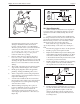
LAARS HEATING SYSTEMS Page 8 Caution Since some leak test solutions (including soap and water) may cause corrosion or stress cracking, the piping must be rinsed with water after testing, unless it has been determined that the leak test solution is noncorrosive. 2E. Electrical Wiring Figure 8. T-Fitting Sediment Trap Installation. 4. 5.
Mighty Therm Volume Water Heater Page 9 Figure 10. Tempering Valve Installation. 2G. Water Expansion Figure 9. Pressure Relief Valve Location. 3. 4. 5. 6. 7. 8. Special attention must be given to relief valve settings in installations where the heater is located on the ground floor of a tall building. The static pressure of the system is elevated and could cause the relief valve to leak. Where no special setting of the relief valve is ordered, the factory will furnish a 125 psi setting.
LAARS HEATING SYSTEMS Page 10 2H. 1. Pump Performance and Installation The factory provided pump on PW heaters and the recommended field provided pump for model VW heaters are sized to provide proper circulation through the heater and heater-totank circulation loop (see Figures 11 and 12).
Mighty Therm Volume Water Heater Page 11 With Vertical Tank With Horizontal Tank NOTES: Heavy line indicates Heater to Tank Circulating Loop. Figure 11. Hot Water Supply System (Model VW & PW).
Page 12 LAARS HEATING SYSTEMS Figure 12. Hot Water Supply System Using Model PW with Dual Tanks, Building Loop Return and Circulating Pump. CAUTION: 1. This piping arrangement is required on split systems to provide constant hot water temperatures. 2. Pipe size and length must conform to the recommendations for each heater model. 3. A loop circulator is required to maintain forced circulation in the building hot water piping system. Figure 13. Split System Piping Diagram, Model IW.
Mighty Therm Volume Water Heater NOTES: 1. All water connections 2" N.P.T. models. 2. Drain valve per ASME requirements. 3. A loop circulator is required to maintain forced circulation in the building hot water piping system. Figure 14. Dual Installation Piping Diagram, Model IW. NOTES: 1. All water connections 2" N.P.T. models. 2. Drain valve per ASME requirements. 3. A loop circulator is required to maintain forced circulation in the building hot water piping system. Figure 15.
Page 14 LAARS HEATING SYSTEMS With Horizontal Tank Legend B - Check Valve in Hot Water Supply to Tempering Valve C - Check Valve in Return Line from Building Loop D - Tempering Valve E - Venturi (Suction) Tee H - Throttling Valves in Building Loop Returns I - Circulating Pump for 180° Building Loop J - Circulating Pump for 140° Building Loop K - Service Valves to Isolate Heater and Pump for Service With Vertical Tank Legend B - Check Valve in Hot Water Supply to Tempering Valve C - Check Valve in Retur
Mighty Therm Volume Water Heater Page 15 Legend B - Check Valve C - Check Valve D - Tempering Valve H - Throttling Valves in Building Loop Returns J - Circulating Pump for Return Loop K - Service Valves to Isolate Heater and Pump for Service Figure 17. Two-Temperature Hot Water Supply System with Vertical Tank for Models VW and PW Water Heaters.
LAARS HEATING SYSTEMS Page 16 Model Water Category Flow Rate (GPM) Head* Loss (ft.) Temp. Rise Across Heater, (°F) 2J. Tank Installation 1. 500 Soft Normal Hard 45 68 90 5.0 9.9 15.7 17 11 8 2. 600 Soft Normal Hard 45 68 90 5.1 10.0 15.9 20 14 10 3. 715 Soft Normal Hard 45 68 90 5.3 11.0 17.8 24 16 12 4. 850 Soft Normal Hard 45 68 90 5.4 11.1 18.1 30 20 15 1010 Soft Normal Hard 45 68 90 3.9 7.5 11.7 35 23 18 1200 Soft** Normal Hard 68 68 90 7.8 7.8 12.
Mighty Therm Volume Water Heater 2. 3. proven to be lit. Whenever the pilot flame is interrupted, the main gas valve closes within 0.8 seconds. b. Electronically Supervised Standing Pilot System (System #16): When pilot flame fails, the ignition control module responds in less than 0.8 seconds and provides 100% safety shutdown. Operating Controls: a.
LAARS HEATING SYSTEMS Page 18 gas supply, the automatic safety shutoff devices must be checked. 1. Before beginning the tests, make sure the main manual gas valve, and any other heater firing valves are in the “OFF” position. 2. Make sure the heater’s power switch is in the “ON” position. After placing the manual pilot gas valve in the open position and resetting all safety devices, (high limit, pressure switch, lowwater cutoff, etc.
Mighty Therm Volume Water Heater Page 19 depressed for one minute then release. Once the pilot is lit, the power is supplied through the aquastat to the main gas valve. 2. To set the temperature and high-limit controls: When using a tank aquastat: Set the tank aquastat to the desired tank temperature. Set the heater temperature control 20°F higher than tank aquastat. Set the manual reset high limit 50°F higher than tank aquastat.
LAARS HEATING SYSTEMS Page 20 Lower the front of the burner (to avoid damaging pilot shield) then remove the burner tray. Caution Black carbon or green soot on a dirty heat exchanger can, under certain conditions, be ignited by a random spark or open flame. To prevent this unlikely occurrence, dampen the soot deposits with wet brush or fine water spray before servicing or cleaning the heat exchanger. 8. 9. With a wire brush, remove soot and loose scale from heat exchanger.
Mighty Therm Volume Water Heater II. HEATER IS POUNDING, KNOCKING OR EMITTING STEAM FROM RELIEF VALVES. Possible Cause A. Low or no water flow. What To Do A. This condition is usually caused by lack of adequate water flow through heater. Check the following: 1. Is the heater wired into the pump circuit so that the heater cannot fire unless the pump is running? 2. Check to see that all valves in system are open to be sure that water can circulate through the heater and the system. 3.
Tile Cover, Front & Rear Baffle, Heat Exch.
Mighty Therm Volume Water Heater Page 23 NOTE: Temperature Control Wells Inlet/Outlet Header 1. Firing Mode L, K, & C 2 Dry Wells 2. Firing Mode H A. Natural Gas Boilers & Heaters 500 thru 850 - 2 Dry Wells 1010 thru 1430 - 3 Dry Wells 1670 thru 1825 - 4 Dry Wells B. Propane Gas Boilers & Heaters 500 thru 850 - 2 Dry Wells 1010 thru 1852 - 3 Dry Wells Figure 22. Parts Identification.
—— —— —— —— 24 Tile, Heat Shield/Spacer, Front 25 Tile, Heat Shield/Spacer, Rear 26 Tile, Heat Shield/Spacer, Rear 27 Tile, Heat Shield/Spacer, Rear 10540501 10531501 10551000 (2) 10540901 10541001 10554601 10554401 10533901 35 Upper Rear Panel/Heat Shield Weldment 36 Front Panel, Upper 37 Brackets, Support, End Tile 38 Drafthood, Relief Baffle, Right 39 Drafthood, Relief Baffle, Left 40 Lower Right Panel/Heat Shield Weldment 41 Middle Front Panel 42 Sweep Sheet, Flue Collector 10533902 10554
Mighty Therm Volume Water Heater Figure 23. Tile Assemblies.
10536901 L0052300 10529501 10529502 48 Base Tile Support Assy.
P0028500 ———— 83 Red. Tee, 2 x 2 x 1, GaIv Red.
Pipe Extension 1/2" Female Pipe Extension 1/2" Male Baffle, Diffuser Burner Tray, IID, 2 Stage, SGL Sect. Manifold (Nat) Burner Tray, St. Pilot, 2 Stage, SGL, Sect. Manifold (Pro) Burner Tray, I I D, 4 Stage, Split Manifold (Nat) —— V0059600 (2) —— V0059600 (2) V0054800 —— V0071100 (3) —— —— V0070900 (2) —— —— 10550501 V0070400 (2) —— 10551201 —— 10550305 10550705 10529605 10550605 P0072300 10338400 Model 1010 P0027000 108 Operating/Reg.
Mighty Therm Volume Water Heater Figure 21. Outdoor Parts.
10658901 10659501 10659301 10660400 16 Front Panel Upper 17 Flue Panel Front 18 Flue Panel Rear 19 Rain Shield-Control Box (Not shown) Rear Panel, Flue Collector Ext.
10667701 (7) 10662001 10662201 10602301 10665901 10670401 10 Baffle, Heat Exchanger 41 Middle Front Panel 42 Sweep Sheet Flue Collector 48 Base Tile Support 69 Tube Assembly, Copper 70 Tube Assembly, Cupro-Nickel 10670402 10665902 10602302 10662202 10662002 10667702 (14) 10661502 (2) 10662102 Model 600 10670403 10665903 10602303 10662203 10662003 10667703 (14) 10661503 (2) 10662103 Model 715 10670404 10665904 10602304 10662204 10662004 10667704 (14) 10661504 (4) 10662104 Mod
SECTION 8. Optional Parts Descriptions and Order Numbers Pump Rotating Sections and Repair Parts Check pump assembly on heater for H.P. rating and find correct Laars part number from table below.