
Technology Brief Understanding Relationships Voltage-Current-Impedance


WWW.LABGRUPPEN.COM
Foreword
This paper addresses general sound reinforcement system design
issues and offers application solutions provided by LAB GRUPPEN
C Series power ampliers. We’ll review these products’ capabilities,
provide guidelines for amplier sizing based on speaker load and,
describe the important relationship between voltage & current.
Let’s begin by identifying 3 core functions of an amplier:
1) Provide clean, undistorted audio power to the speakers
2) Protect the speakers from excessive signals and abuse
3) Protect the amplier itself under all conditions
System Design
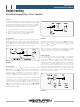
The purpose of a quality engineered sound reinforcement system
design is to deliver the program at the required Sound Pressure
Level or SPL to a listener’s position. We begin by selecting a speaker
system, placing it at some distance ‘d’ from the listener and delivering
‘P
SPKR
’ watts of power from an Amplier as shown in gure 1.
FIGURE 1
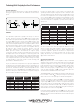
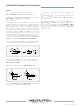
Acoustic Design
In the Acoustic Design, the ‘P
NOM
’ which is the nominal power and,
‘P
MAX
’ which is the maximum power, dictate the size amplier we
need given the target SPL. Both power levels must be identied
to properly match the amplier for the speaker’s characteristic
impedance or ‘R
LOAD
’ (8 ohm, 4 ohm, 2 ohm, etc.) Let’s look at a few
factors concerning the Acoustic Design while referring to gure 2.
Sound decreases in level 6dB for every doubling of distance ‘d’ from
the speaker; e.g. 60 feet is -6 dB compared to 30 feet and 120 feet is
-6 dB compared to 60 feet. The speaker’s specied sensitivity is its
output SPL, measured typically at 1 Meter on axis when driven with
1 Watt. Most manufacturers will specify this as the ‘dB
SPL
/W/M’
sensitivity value for their product along with the maximum power
handling capability or ‘P
MAX
’.
FIGURE 2
Knowing the speaker sensitivity and the target ‘dB
SPL
’ at the listener
position, we can calculate for the nominal power required at the
speaker or ‘P
NOM
’. The ‘P
NOM
’ should not exceed ‘P
MAX
’ else the
speaker may be overdriven.1
When the speaker is selected and the nominal power PNOM
requirements have been determined for the target SPL at the listener
we can then specify the correct type and size of amplier.
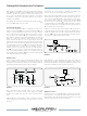
Electrical Design
In the Electrical Design, we’ll choose an amplier with a maximum
power output ‘P
AMP
’ at the load impedance ‘R
LOAD
’ that is greater
than or equal to ‘P
MAX
’. You must also factor for additional power or
“headroom” to ensure the amplier does not clip or distort when
delivering its’ maximum power or P
MAX
. Headroom is the difference
in dB between the nominal operating level you expect from the
system and the maximum output or clip level. The goal is to design
a system with a properly sized amplier that is gain matched for the
nominal input signal levels from the console and provides sufcient
headroom (in the range of +6 dB to +20 dB) so that the peak power
levels are delivered without clipping.
FIGURE 3
WWW.LABGRUPPEN.COM
Technology Brief
Designing for Great Performances
Understanding
Relationships between Voltage - Current - Impedance