Rev. 3.0.4 Item no.
1. Important safety instructions 1. Important safety instructions Before using the device, be sure to carefully read the Safety Instructions. Keep this document with the device at all times. 1. 2. 3. 4. 5. 6. 7. 8. 9. 10. 11. 12. 13. 14. 15. 16. 17. 18. 19. 20. 21. 22. 22 Read these instructions. Keep these instructions Heed all warnings. Follow all instructions. Do not use this apparatus near water. Clean only with a dry cloth. Do not block any ventilation openings.
. Warnings To completely disconnect this equipment from the AC mains, disconnect the power supply cord plug from the AC receptacle. The mains plug of the power supply cord shall remain readily operable. Français: Pour démonter complètement l’équipement de l’alimentation générale, démonter le câble d’alimentation de son réceptacle. La prise d’alimentation restera aisément fonctionnelle. To reduce risk of fire or electric shock, do not expose this apparatus to rain or moisture.
. Table of Contents 4. Table of Contents 1. Important safety instructions 2 2. Approvals 2 3. Warnings 2 3.1. Explanation of warning symbols 2 3.2. Warnings 2 3.3. Caution 3 3.4. User responsibility 3 5. Introduction 6 5.1. Welcome 6 5.2. D Series: Two versions available 6 5.3. Feature summary 7 6. Installation 8 6.1. Unpacking 8 6.2. Mounting 9 6.3. Cooling and fan operation 10 6.4. Operating voltage 10 6.5. Grounding 11 7. Product overview 12 7.1. Front panel 12 7.
4. Table of Contents 10. Rear panel interface 18 11. Operation and performance 19 11.1. Operation precautions 19 11.2. Power output performance 19 21 11.4. Power Supply 28 11.5. Auto power down 29 11.6. LoadPilot Load Monitoring 30 33 12. Lake Processing and Lake Controller 12.1. Introduction 33 12.2. Modules and Frames 33 12.3. Lake LoadLibrary™ and Fingerprints 34 12.4. Loudspeaker Processor Overview 34 34 34 12.6. Frame and System Presets 35 35 13.1. Network setup 36 13.3.
5. Introduction 5. Introduction 5.1. Welcome Thank you for choosing the Lab.gruppen D Series for your sound offered by this product. For fast installation and use of this product, your welcome package includes a printed copy of the D Series Quick Start Guide (QSG). It provides a brief introduction to the features and functionality of the D Series and it also contains the information required to safely install the product and place it in service.
5. Introduction 5.3. Feature summary 5.3.1. Features common to both D Series variants • Four channels with six levels of total available frame power output: 20000 W, 12000 W, 8000 W, 4000 W, 2000 W and 1000 W • Rational Power Management (RPM) • True flexibility in allocating power output across each channel to match requirements, for more efficient use of amplifier inventory • Any channel is capable of being significantly scaled up to match power requirements.
6. Installation 5.3.3. Other Documentation This Operation Manual is intended to serve as a guide and reference to the operation and maintenance of the D Series Lake hardware platform. Comprehensive information is given regarding installation, connection and operation of the front panel interface. D Series Lake amplifiers are designed for configuration and operation using the Lake Controller and CAFÉ software programs.
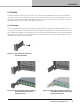
6. Installation 6.2. Mounting D Series is made for mounting in 19 inch racks. Four screw holes are available for attachment of the amplifier to the racks front rack rail. This device has no top or bottom vents; therefore, units may be stacked directly on top of one another. Sufficient space should be available at the rear to accommodate connectors and cables. In addition, allowance must be made for cable or loom bends within a rack. 6.2.1.
6. Installation 6.2.2. Mounting front grille The front grille is shipped on top of the amplifier inside the box to protect it during shipping. The front grille adheres to the amplifier with magnets. Hold the front grille with your fingers in each of the side cutouts and slide it gently into place straight from the front. NOTE: Always ensure the dust filters behind the detachable front panel are clean to ensure maximum possible airflow.
6. Installation 6.4.1. Low voltage country considerations Although the D Series has a wide range of operating mains voltage, some considerations can be applicable for low voltage regions. D Series performs well throughout the specified nominal voltage range but has slightly better efficiency at higher voltages.
7. Product overview 7. Product overview 7.1. Front panel 1 1 The front panel consists of an outer front with air intake and a centered user interface. The user interface has LEDs for monitoring and six recessed touch buttons for control. 1 2 Rack ears for 19 inch rack mount Exterior front grille (also air intake and dust filter holder) 3 3 12 12 Touch and LED panel – See section 9.1 for further information. SERIES Lake Lake Operation Operation Manual Manual rev 3.0.4 DD SERIES 3.0.
7. Product overview 7.2.
Signal flow, routing and mute points 7.8.Product overview 8. Signal flow, routing and mute points 8.1. Signal flow device provides seven points in the signal chain where the signal level can be adjusted, muted or disconnected.
9. Front panel interface 9. Front panel interface 9.1. Frame status and control 1 3 2 4 5 7 6 8 9 NOTE: General status indication shown in Table 9.1. For detailed information on warning and fault indication, please refer to the Faults and Warnings table in Section 14.1.
9. Front panel interface OFF Green Amber Red Frame N/A Frame OK Frame warning Frame fault Temp N/A Temp OK Temp warning Temp fault PSU N/A PSU OK Power supply/ Mains warning Power supply/ Mains fault Power No mains power Fixed:ON Blinking: Turning ON Button pressed.
9. Front panel interface 9.4. Additional front panel operations and indications 9.4.1. Frame reset A factory reset and soft reset can be performed from the front panel. A factory reset will restore all settings to original defaults, including network settings, frame presets and current settings. A soft reset reverts only the current settings to default. Network settings and frame presets are not changed with a soft reset. 6. Place the frame in standby mode. 7.
10. Rear panel interface 10. Rear panel interface 1 3 2 4 5 2 1 2 3 4 3 4 1 5 nnect loudspeaker cables to the mating plug–in connectors observing polarity (including bridge mode option for D200, D120 and D80) as marked on the rear panel Analog Inputs – Analog inputs are available on terminal block connectors with clearly marked hot (+), cold (–) and ground terminals.
11. Operation and performance Secondary Connector – The secondary network connector can be used to create a Dante dual–network topology by connecting all secondary network connectors to a separate Ethernet switch, ensuring full redundancy in the event of a network component failure. Alternatively, the secondary network connector can be used to daisy–chain multiple Lake devices (LM, PLM, PLM+ or D Series), if Dual Redundancy is Disabled from the Lake Controller.
11. Operation and performance 11.2.1. Symmetrical power D Series models can deliver power as shown in Table 11.1 when all channels are driven equally. 2 ohms 2.
11. Operation and performance 2000 W SUB LOW MID HIGH D Series -11.2: Amp channels power adjusted to match the loudspeaker requirements Figure Amp channels power adjusted to match the loudspeaker requirements on a D 80:4 Auto RPM: The frame will automatically allocate power per output channel according to the ISVPL settings in the speaker preset (per module output) in Lake Controller. Auto RPM assumes a nominal impedance of the Load and applies an approximate power allocation.
11. Operation and performance 11.3.1. Inter–Sample Voltage Peak Limiter (ISVPL) The ISVPL is a high quality voltage limiter that can deliver seamless limitation to any desired level. It ensures that the voltage at the output terminals never exceeds the defined threshold. It operates on these principles: • The signal is delayed slightly to allow the ISVPL to look–ahead and reduce the gain before voltage in excess of the threshold can appear at the output.
11. Operation and performance Max. Sinewave Burst Power (Watts) LLoad Impedance (ohms) 2 2.
11. Operation and performance PAL activity is shown by PSU amber LED indication and a corresponding text description in Lake Controller and CAFÉ software programs. Refer to Section 14.1 for more information on warnings and faults. 11.3.4. Breaker Emulation Limiter (BEL™) The BEL models the temperature in the external breaker and limits the mains current to prevent the breaker be selected for Frame Replace support). The desired nominal current value can be set from 1 to 32 Arms.
11. Operation and performance NOTE: For Slimeline models, to optimize the CAL’s behavior when playing into a low impedance load, manually set the desired ISVPL to reflect the real peak voltage output to allow for a higher average current. 11.3.7. Voltage Clip Limiter (VCL) If current draw from the unit’s power supply is too high, the PSU’s regulation capability may be exceeded and the internal voltage rails may drop and cause clipping.
11. Operation and performance channel Temperature Limiter (ATL) will engage at approximately 95% of the maximum allowable temperature. When ATL is engaged, it will try to reduce the power output to avoid that the amp channel goes into temp fault, i.e. muting. Limiting is removed when temperature falls below the ATL threshold. 11.3.8.2. Power Supply / DSP A power supply (PSU) or DSP temperature warning or fault is indicated by the Temp LED.
11. Operation and performance Trigger voltage 100 90 Voltage [Vrms] 80 70 60 50 40 30 20 10 0 0 5 10 15 20 25 30 Frequency [kHz] Fig 11.4: VHF Protection Frequency Sensitivity The attack time of the VHF protection circuitry also changes with frequency, becoming shorter at higher frequencies. This is shown in Figure 11.5. Full output voltage 1400 1200 Time [ms] 1000 800 600 400 20 200 0 0 5 10 15 20 25 30 Frequency [kHz] Fig 11.
11. Operation and performance The presence of a short circuit (or low impedance) is re–tested every six seconds, and the output remains muted until the fault clears. 11.3.12. Power supply protection The power supply is very advanced and has several internal control and monitoring functions. Should any of these fail, the power supply will shut down to prevent damage or limit severity of the failure. If the power supply shuts down audio will be muted.
11. Operation and performance D Series features a universal power supply with power factor correction (PFC). The device can accept any mains voltage, from 65 V to 265 V, allowing it to function worldwide in many different configurations. The PFC reduces current peaks on the lines and reduces the requirements placed on the mains distribution system. D Series units offer an unparalleled power factor extremely close to one. 11.4.1.
11. Operation and performance 11.6. LoadPilot Load Monitoring 11.6.1. Introduction LoadPilot is a feature in D Series amplifiers that can continually monitor the integrity of loudspeakers and cables connected to the outputs to ensure that they are functioning properly and free from major anomalies or faults. By implementing LoadPilot, systems incorporating D Series amplifiers can be certified in compliance with voice evacuation standards such as EN54–16 and NFPA72.
11. Operation Operation and and performance performance 11. 11.6.3. Manual configuration 11.6.3.1. Functional description Manual configuration can be used in special cases where proper functioning requires setting of custom measurement frequencies, custom measurement levels, custom warning thresholds, or combinations of the three.
11. Operation and performance 12. Lake Processing and Lake Controller 11.6.4. Indication The LoadPilot feature constantly monitors the impedances at the two given pilot tone frequencies and compares to the measured thresholds. The following faults and warnings can be triggered. • Speaker shorted warning – Both tones below lower threshold. Corresponds to a distant short circuit that can either be in the cabling or in the speaker. • Speaker damaged warning – One of the tones is below or above thresholds.
12. Lake Processing and Lake Controller 12. Lake Processing and Lake Controller 11.7.2. AES67 When the device is in AES67 enable mode, the device is in 48 kHz only (also for Dante subscriptions/transmissions). The receiver latency for AES67 subscriptions is 2 ms. Transmission flows are Multicast only. AES67 subscriptions can only be configured in Dante Controller. The AES67 transmitter must support the SAP (Session Announcement Protocol).
12. Lake Processing and Lake Controller 12. Lake Processing and Lake Controller 12.3. Lake LoadLibrary™ and Fingerprints as SpeakerPresets are available in the Lake LoadLibrary, Additionally, Lake LoadLibrary loudspeaker types may also include data relating to the electrical characteristics of a on the device. This data set is termed a Fingerprint. When a sp 12.4.
13. System configuration tutorial 13. System configuration tutorial Using the System Presets function in the Lake Controller, entire system configurations can be stored and recalled across a network of Lake devices, including D Series Lake, LM, PLM and PLM+ Series devices. This enables fast retrieval and switching of entire system configurations as minimal data is being sent between the Controller and Processors. 13.
13. System configuration tutorial 13. System configuration tutorial (which should be default on modern operating systems), it will reside in the same subnet as the devices and address in the 172.31.0.0 – 172.31.255.255. 13.2. Software installation and firmware update 13.2.1. Lake Controller software suite 1. The Lake controller software suite includes the Lake controller and accompanying utilities: Lake LoadLibrary, Dante discovery services and documentation.
13. System configuration tutorial 13. System configuration tutorial 13.3. System setup This tutorial provides a step–by–step guide for configuration of a typical professional loudspeaker system and provides an overview of the basic features and operation of the frame. This tutorial describes how to configure 4–channel frame for use with a generic 3–way loudspeaker system (with separate HF, MF and LF drivers), plus a separate subwoofer.
13. System configuration tutorial Bridge 13. System configuration tutorial Bridge 1 2 3 4 14. The B module is already a CL1way as default and can be used to drive the sub. 15. Tap Store/Recall EXIT to return to the Modules Menu. 16. Ensuring Module A (or any other module that you want to control) is selected (yellow border), tap I/O Config. 17. The right side of the I/O CONFIG screen displays a block diagram for the Modules.
13. System configuration tutorial Levels Control – Drag sliders and tap mute buttons for module input and output channels. Delay Control – Drag sliders to control input and output delay 13. System configuration tutorial Parametric EQ control – Select filter on the top squares and adjust filter properties by dragging the controls. Sliders at the bottom control center frequency and Q (bandwidth). Gain is controlled in the main window area.
13. System configuration tutorial 13. System configuration tutorial 21. Repeat step 16 and 20 for the B module. On the Output EQ/Crossover, tap the Aux Output Functions button on the menu bar and then tap LPF Enable button. Drag the Low pass filter control object on the frequency slider just above the menu bar to an appropriate crossover frequency for the sub, e.g. 100 Hz. 22. Use the control options mentioned in 17 to tune your loudspeakers.
14. Appendix 14. Appendix 14. Appendix 14.1. Faults and warnings Category/Type Name On screen text Description Action Warning Lake Controller offline CTRL OFFLINE Frame unable to find Lake controller on the network Check network cabling/ network if controller expected on the network Warning AES / Dante clock slipping CLOCK SLIPPING Frame not able to lock to incoming AES stream or Dante clock slipping.
14.
14. Appendix 14.2. Current draw and thermal dissipation D SERIES 10:4 Level Load Rated power per channel Line Current (A) Measured Power (W) In Out Thermal Dissipation Dissipated BTU/hr kCal/hr Mains Voltage 100 VAC Standby 0.1 7 0 7 24 6 Power On, Idling, Green Mode 0.5 45 0 45 153 38 Power On, Idling, Performance Mode Pink Pseudo Noise 16 Ω / Ch. 250 x 4 8 Ω / Ch. 250 x 4 4 Ω / Ch. 250 x 4 0.7 71 0 71 241 61 2.3 229 125 104 355 89 2.4 240 125 115 391 98 2.
14. Appendix D SERIES 20:4 Level Load Rated power per channel Line Current (A) Measured Power (W) In Out Thermal Dissipation Dissipated BTU/hr kCal/hr Mains Voltage 100 VAC Standby 0.2 7 0 7 24 6 Power On, Idling, Green Mode 0.5 46 0 46 157 39 Power On, Idling, Performance Mode Pink Pseudo Noise 0.7 71 0 71 243 61 16 Ω / Ch. 425 x 4 2.9 348 213 136 463 117 8 Ω / Ch. 500 x 4 3.5 418 250 168 573 144 4 Ω / Ch. 500 x 4 3.7 444 250 194 662 167 2 Ω / Ch.
14. Appendix Appendix 14. D SERIES 40:4 Level Load Rated power per channel Line Current (A) Measured Power (W) In Out Thermal Dissipation Dissipated BTU/hr kCal/hr Mains Voltage 100 VAC Standby 0.2 7 0 7 24 6 Power On, Idling, Green Mode 0.6 59 0 59 201 51 Power On, Idling, Performance Mode Pink Pseudo Noise 0.8 78 0 78 267 67 16 Ω / Ch. 700 x 4 5.1 502 350 152 518 131 8 Ω / Ch. 1000 x 4 7.2 709 500 209 714 180 4 Ω / Ch. 1000 x 4 7.
14. Appendix D SERIES 80:4 Level Load Rated power per channel Line Current Power Factor (A) (%) Measured Power (W) In Out Thermal Dissipation Dissipated BTU/hr kCal/hr Mains Voltage 100 VAC, 30 A Standby 0.3 43 11 0 11 36 9 Power on, Idling 2.1 99 204 0 204 696 175 Pink Pseudo Noise LoadPilot Sine 20 kHz 16 Ω / Ch. 750 10.1 99 981 375 607 2070 522 8 Ω / Ch. 1500 15.3 99 1492 749 743 2534 639 4 Ω / Ch. 2000 14.9 99 1502 652 850 2900 731 2.67 Ω / Ch.
14. Appendix D SERIES 120:4 Level Load Rated power per channel Line Current Power Factor (A) (%) Measured Power (W) In Out Thermal Dissipation Dissipated BTU/hr kCal/hr Mains Voltage 100 VAC, 30 A Standby 0.3 43 12 0 12 40 10 Power on, Idling 2.3 98 219 0 219 749 189 503 Pink Pseudo Noise LoadPilot Sine 20 kHz 16 Ω / Ch. 950 10.8 99 1059 475 584 1994 8 Ω / Ch. 1900 19.2 99 1868 949 919 3136 791 4 Ω / Ch. 3000 24.6 99 2389 1200 1189 4057 1023 2.
14. Appendix D SERIES 200:4 Level Load Rated power per channel Line Current Power Factor (A) (%) Measured Power (W) In Out Thermal Dissipation Dissipated BTU/hr kCal/hr Mains Voltage 100 VAC, 30 A Standby 0.3 52 17 0 17 58 15 Power on, Idling 2.4 97 235 0 235 802 202 Pink Pseudo Noise LoadPilot Sine 20 kHz 16 Ω / Ch. 1150 12.1 99 1192 588 604 2061 520 8 Ω / Ch. 2300 22.3 99 2198 1174 1024 3493 881 4 Ω / Ch. 4400 29.2 99 2853 1478 1375 4691 1183 2.
14. Appendix 14.3. Maintenance During normal operation a D Series device provides trouble–free service. If the front panel display requires cleaning, use a soft cloth only; do not use solvent cleaners. The dust filters on both sides of the front panel, behind the grilles, should occasionally be removed and cleaned to ensure maximum airflow through the device. Disconnect the unit from mains power prior to removing dust the filter, and ensure the dust filter is replaced prior to turning the unit back on.
15. Technical Specifications 15. Technical Specifications D 200:4L D 120:4L D 80:4L Total burst power all channels (share among channels with RPM) Lake / Dante 4 20000 W Lake / Dante 4 12000 W Lake / Dante 4 8000 W Max. Output Power (all ch.’s driven) 1) 2 ohms 2.67 ohms 4 ohms 8 ohms 16 ohms Hi-Z 70 V Hi-Z 100 V 4400 W 5000 W 4400 W 2300 W 1150 W 3300 W 4700 W 3000 W 3000 W 3000 W 1900 W 950 W 3000 W 3000 W 2000 W 2000 W 2000 W 1500 W 750 W 2000 W 2000 W Max. Output power bridged mode (all ch.
15. Technical Technical Specifications Specifications 15.
15. Technical Specifications D 40:4L D 20:4L D 10:4L Total burst power all channels (share among channels with RPM) Lake / Dante 4 4000 W Lake / Dante 4 2000 W Lake / Dante 4 1000 W Max. Output Power (all ch.’s driven) 1) 2 ohms 2.67 ohms 4 ohms 8 ohms 16 ohms Hi-Z 25 V Hi-Z 70 V Hi-Z 100 V 800 W 1000 W 1000 W 1000 W 700 W 500 W 1000 W 1000 W 500 W 500 W 500 W 500 W 425 W 500 W 500 W 250 W 250 W 250 W 250 W 250 W 250 W 250 W 250 W 175 W Max output power single channel 1) 2 ohms 2.
15. Technical Specifications AES Inputs Inputs Supported sample rates / resolution Sample rate conversion THD + N 20 Hz - 20 kHz unweighted Back panel interface Analog inputs AES inputs Output connectors D 40:4L D 20:4L D 10:4L 4 AES inputs 44.1, 48, 88.2, 96, 176.4, 192 kHz / up to 24 bit 0.00003 % 4 x Terminal block connectors analog input with +, - and ground 4 x Terminal block connectors analog input with +, - and ground Ethernet ports Detachable mains cord to 8 mm2 (8.
16. Warranty and support 16. Warranty and support 16.1. General This product is manufactured by Lab.gruppen, and it is warranted to be free from any defects caused by components or factory workmanship, under normal use and service, for a period of ten (10) years from date of purchase from an authorized Lab.gruppen dealer. If the product fails to perform as specified during the warranty period, Lab.
16. Warranty and support 16.2.2. Factory service In the event a Lab.gruppen product requires factory service, you may contact Lab.gruppen’s service department for return instructions and a Return Authorization number. Please note for product return: 1. Use the original packing. 2. Include a copy of the sales receipt, your name, return address, phone and fax number, email address and description of the defect. 3. Mark the Return Authorization number on the outside of the packing.
Notes Notes 56 D SERIES Lake Operation Manual rev 3.0.4 D SERIES Lake Operation Manual rev 3.0.
Notes Notes 56 D SERIES Lake Operation Manual rev 3.0.3 D SERIES Lake Operation Manual rev 3.0.
Lab.gruppen adopts a policy of continuous improvement and product specification is subject to change. RPM, R.SMPS, PFC, CDM, BEL, UVL, CAFÉ, ESP, ISVPL, Iso–Float, Raised Cosine, MESA EQ, LimiterMax and LoadLibrary are trademarks of Lab.gruppen AB. All other trademarks remain the property of their respective owners. Copyright © 2018 Tribe Brands Innovation Sweden AB. All rights reserved. Item no. OM–DSERIES–LAKE labgruppen.