
Quick Start Guide


12. Signal flow and processing
D SERIES Tesira Quick Start Guide rev 2.2.0
25
12. Signal flow and processing
12.1. Signal flow
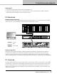
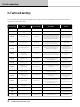
The table below depicts the audio signal ow for a D Series Tesira device.
Figure 8.1: D Series Tesira Signal Flow Diagram
1
The Tesira system is a free-wire DSP environment where processing features can be designed and distributed
among servers. System IO is designed and managed, and all signal processing is dened, at the server level.
D Series Tesira ampliers are added as high power outputs to the system with audio transported to them via
the AVB network, through an analog connection, or both.
2
AVB is a distributed network of one or more Ethernet AVB-enabled switches that carry both networked audio
and control.
3
Mute block in the Tesira output section
4
Level block in the Tesira output section
5
Invert block in the Tesira output section
6
Amplier gain - Digitally implemented for exact control and management of gain structure
7
ISVPL/RPM - Inter-sample Voltage Peak Limiter is a digitally implemented voltage peak limiter with assignable
proles. Rational Power Management conguration enables exible power sharing of the total available power
across the amplier channels.
8
Load monitoring - Impedance sweeps and LoadPilot monitoring
Mute Level Invert AmpGain RPM/ISVPL
Load
Monitoring
Mute Level Invert AmpGain RPM/ISVPL
Load
Monitoring
Mute Level Invert AmpGain RPM/ISVPL
Load
Monitoring
Level AmpGain RPM/ISVPL
Load
Monitoring
D Series Tesira Amplifier
1
2
3 4 5 6 7 8
Mute Invert
Tesira
Environment
Amplifier
Platform
AVB
Network
Tesira
free-wire DSP
processing
hosted by
Tesira
servers