Rev. 1.0.0 Item no.
1. Important safety instructions 1. Important safety instructions Before using the device, be sure to carefully read the Safety Instructions. Keep this document with the device at all times. 1. 2. 3. 4. 5. 6. 7. 8. 9. 10. 11. 12. 13. 14. 15. 16. 17. 18. 19. 20. 21. 22. 2 Read these instructions. Keep these instructions Heed all warnings. Follow all instructions. Do not use this apparatus near water. Clean only with a dry cloth. Do not block any ventilation openings.
. Warnings To completely disconnect this equipment from the AC mains, disconnect the power supply cord plug from the AC receptacle. The mains plug of the power supply cord shall remain readily operable. Français: Pour démonter complètement l’équipement de l’alimentation générale, démonter le câble d’alimentation de son réceptacle. La prise d’alimentation restera aisément fonctionnelle. To reduce risk of fire or electric shock, do not expose this apparatus to rain or moisture.
. Table of Contents 4. Table of Contents 1. Important safety instructions 2 2. Approvals 2 3. Warnings 2 3.1. Explanation of warning symbols 2 3.2. Warnings 2 3.3. Caution 3 3.4. User responsibility 3 5. Introduction 6 5.1. Welcome 6 5.2. D Series: Two versions available 6 5.3. Feature summary 7 6. Installation 8 6.1. Unpacking 8 6.2. Mounting 9 6.3. Cooling and fan operation 10 6.4. Operating voltage 10 6.5. Grounding 11 7.
4. Table of Contents 10. Rear panel interface 18 10.1. Amplifier Outputs 18 10.2. RJ-45 Ethernet Connector 18 10.3. RS-232 and GPIO ports 18 10.4. Analog inputs (Tesira analog version only) 21 10.5. Mains connector 21 11. Operation and performance 22 11.1. Operation precautions 22 11.2. Power output performance 22 11.3. Amplifier and Load Protection Systems 24 11.4. Power Supply 30 11.5. LoadPilot Load Monitoring 31 12.
5. Introduction 5. Introduction 5.1. Welcome Thank you for choosing the Lab.gruppen D Series for your sound reinforcement needs. We are confident that you will be pleased with the performance, unique features, configuration flexibility, reliability, and long–term durability offered by this product. For fast installation and use of this product, your welcome package includes a printed copy of the D Series Quick Start Guide (QSG).
5. Introduction 5.3. Feature summary 5.3.1.
6. Installation 5.3.3. Other Documentation This Operation Manual is intended to serve as a guide and reference to the operation and maintenance of the D Series Tesira hardware platform. Comprehensive information is given regarding installation, connection and operation of the front panel interface. D Series Tesira amplifiers are designed for configuration and operation using the Tesira software and CAFÉ software programs.
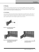
6. Installation 6.2. Mounting D Series is made for mounting in 19 inch racks. Four screw holes are available for attachment of the amplifier to the rack’s front rack rail. This device has no top or bottom vents; therefore, units may be stacked directly on top of one another. Sufficient space should be available at the rear to accommodate connectors and cables. In addition, allowance must be made for cable or loom bends within a rack. 6.2.1.
6. Installation 6.2.2. Mounting front grille The front grille is shipped on top of the amplifier inside the box to protect it during shipping. The front grille adheres to the amplifier with magnets. Hold the front grille with your fingers in each of the side cutouts and slide it gently into place straight from the front. NOTE: Always ensure the dust filters behind the detachable front panel are clean to ensure maximum possible airflow.
6. Installation 6.4.1. Low voltage country considerations Although the D Series has a wide range of operating mains voltage, some considerations can be applicable for low voltage regions. D Series performs well throughout the specified nominal voltage range but has slightly better efficiency at higher voltages. For regions with nominal voltage below 140 V, one could consider connecting the amplifier in a three–phase delta or two phase split–phase configuration.
7. Product overview 7. Product overview 7.1. Front panel 1 The front panel consists of an outer front with air intake and a centered user interface. The user interface has LEDs for monitoring and six recessed touch buttons for control.
7. Product overview Table 1 LED/category chart NOTE: See Faults and warnings for a detailed description of status, faults and warnings associated with each LED.
7. Product overview 7.2. Rear panel 1 2 3 4 6 5 ANALOG OPTION 1 2 3 4 5 6 14 Amplifier Outputs – Terminal block connectors. See Section 10 for connector rating. RJ-45 Ethernet connector for control and Ethernet AVB digital audio network Serial control port on a DB-9 for integration control Terminal block connector for Logic I/O (4 pins of GPIO and a ground) Analog inputs (optional, Tesira analog version only) Mains connector – Detachable Neutrik powerCON. See Section 10 for connector rating.
8. Signal flow and processing 8. Signal flow and processing 8.1. Signal flow The table below depicts the audio signal flow for a D Series Tesira device.
9. Front panel interface 9. Front panel interface 9.1. Frame status and control 1 3 2 4 5 7 6 8 9 NOTE: General status indication shown in Table 9.1. For detailed information on warning and fault indication, please refer to the Faults and Warnings table in Section 14.1.
9. Front panel interface 9.3. Frame select and ID 9 SELECT LED and TOUCH BUTTON – Selects mode and indicates control between computer software and unit. A single touch on the button will select the unit in supported computer software views. In the other direction, when selecting the unit in a supported computer software view, the LED will indicate the unit is selected by illuminating.
10. Rear panel interface 10. Rear panel interface 1 2 3 4 6 5 ANALOG OPTION 10.1. Amplifier Outputs 1 The amplifier outputs utilize mating Phoenix-type connectors. Connect loudspeaker cables to the mating plug-in connectors observing polarity (including bridge mode option) as marked on the rear panel connectors. See Section 15 for connector rating. 10.2.
10. Rear panel interface 10.3.2. Serial Port 3 The RS-232 interface may be used for external control of the power state. The port utilizes a DE-9 jack and operates at 9600 baud with 8 data bits, 1 stop bit, and no parity bits. These settings cannot be modified. Pin 5 Pin 1 Pin 6 Pin Function Direction 1 DCD Output 2 RXD Output 3 TXD Input 4 DTR Input 5 GND Ground 6 DSR Output 7 RTS Input 8 CTS Output 9 RI Not used Shell GND Ground NOTE: The port is DCE type.
10. Rear panel interface While in SLEEP state, only wake and status commands are available. The Set Power command is available only in the ON or STANDBY state. In order to set the power state from the SLEEP state, it is necessary to first wake the device by using the Wake command. While in the ON or STANDBY state, an error will be returned as a text response of ERR if an unrecognized command or an invalid power value is received. While in the SLEEP state no error is returned.
10. Rear panel interface 10.4. Analog inputs (Tesira analog version only) 5 Four analog inputs are available on terminal block connections with clearly marked hot (+), cold (-) and ground terminals. All inputs are balanced mic or line level input with selectable +48 V phantom power and digitally controlled input gain. Maximum input and digital reference is +24 dBu and input impedance is 8 k ohm. Sampling rate is 48 kHz with 24 bit resolution.
11. Operation and performance 11. Operation and performance 11.1. Operation precautions Make sure that the Standby button on the unit’s front panel is either unlit (OFF), or red (STANDBY), before making any input or output connections. Ensure the AC voltage is within the range printed on the label adjacent to the AC mains connector. Ensure no input signal is present when powering on the unit to reduce the risk of any inadvertent bursts of high level audio. 11.2.
11. Operation and performance Desired power can be specified in several domains: burst and peak power; peak and RMS voltage; and also the speaker’s AES power rating. By specifying the nominal impedance of the load, the RPM algorithms have all input data required to calculate resulting RPM settings. If the desired RPM settings taken together allow total output higher than the capabilities of the amplifier, RPM will reduce actual RPM configuration evenly based on a proportional reduction in dB.
11. Operation and performance 11.3. Amplifier and Load Protection Systems The D Series is equipped with a comprehensive set of protection circuits. If operating conditions become sufficiently extreme that any of these circuits become active, indication is provided by amber or red LEDs on the front panel, and by text notifications in the Tesira software and CAFÉ software. Refer to Section 14.1 for more information on warnings and faults. 11.3.1.
11. Operation and performance Max. Sinewave Burst Power (Watts) LLoad Impedance (ohms) 2 2.
11. Operation and performance 11.3.3. Power Average Limiter (PAL) The Power Average Limiter Active warning (PAL Active) will be displayed when the power supply’s maximum rated design parameters are reached. When this warning is displayed, gain limiting is being applied to the signal and the ISVPL threshold is lowered accordingly. PAL activity is shown by PSU amber LED indication and a corresponding text description in Tesira and CAFÉ software programs. Refer to Section 14.
11. Operation and performance protect the channel. The CAL should not be activated in normal usage. If activated, this is shown by amber or red indication on the Amp LED of the affected output channel and a corresponding text description in Tesira and CAFÉ software programs. Refer to Section 14.1 for more information on warnings and faults 11.3.7.
11. Operation and performance 11.3.8.3. Power Supply / DSP A power supply (PSU) or DSP temperature warning or fault is indicated by the Alarm LED. • A warning is indicated by static amber LEDs • Power supply Temperature Limit (PTL) is indicated by an amber LED • A fault is indicated with static red LEDs When the power supply reaches the temperature warning threshold, the Power supply Temperature Limiter (PTL) is engaged.
11. Operation and performance The attack time of the VHF protection circuitry also changes with frequency, becoming shorter at higher frequencies. This is shown in Figure 11.5. Full output voltage 1400 1200 Time [ms] 1000 800 600 400 20 200 0 0 5 10 15 20 25 30 Frequency [kHz] Fig 11.5: VHF Protection Attack Time Variations The VHF protection circuit is NOT a limiter and does not alter the amplifier’s frequency response. It is implemented solely to detect continuous VHF content.
11. Operation and performance 11.3.13. Mains anomaly protection D Series amplifiers incorporate several features to ensure continuous operation in case of irregularities in the AC mains service. Over–voltage – If the power supply detects mains voltage above 400 V peak or 270 V RMS, it will enter protective shut down mode. The amplifier will auto–restart if the condition clears. Fault will be indicated by a red LED and associated error messages will register in Tesira and CAFÉ software programs.
11. Operation and performance 11.5. LoadPilot Load Monitoring 11.5.1. Introduction LoadPilot is a feature in D Series amplifiers that can continually monitor the integrity of loudspeakers and cables connected to the outputs to ensure that they are functioning properly and free from major anomalies or faults. By implementing LoadPilot, systems incorporating D Series amplifiers can be certified in compliance with voice evacuation standards such as EN54–16 and NFPA72.
11. Operation and performance 11.5.3. Manual configuration 11.5.3.1. Functional description Manual configuration can be used in special cases where proper functioning requires setting of custom measurement frequencies, custom measurement levels, custom warning thresholds, or combinations of the three. Manual configuration addresses the following issues: Speakers with non-stable impedance – For the LoadPilot feature to function the load itself needs to have a stable impedance at the frequency of the tone.
12. Tesira processing environment 11.5.4. Indication The LoadPilot feature constantly monitors the impedances at the two given pilot tone frequencies and compares these to the measured thresholds. The following faults and warnings can be triggered: • Speaker shorted warning – Both tones below lower threshold. Corresponds to a distant short circuit that can either be in the cabling or in the speaker. • Speaker damaged warning – One of the tones is below or above thresholds.
13. Tutorial: Basic system configuration 13.1.2. Firmware update The firmware for the D Series amplifier is contained within the Tesira server. Potential firmware updates of the D Series amplifiers are managed by the Tesira servers. Update Tesira server firmware 1. Download Tesira Firmware from biamp.com: www.biamp.com/products/tesira/downloads.aspx. Locate the Software and Firmware section and download the latest version of Tesira firmware. 2.
13. Tutorial: Basic system configuration 13.2. Network setup Network connections/topology The following diagram shows a typical setup with Tesira software running on a PC. A Tesira server has separate network ports for control and AVB but D Series has these combined into one port. BIAMP SYSTEMS assembled in the USA www.biamp.com SERVER-IO 14 13 12 11 10 9 8 7 6 5 4 3 2 1 SNC-1 Logic I/O +5V 4 3 2 1 Primary Primary Secondary Secondary 100 - 240V~ 50/60Hz 5.5 - 2.
13. Tutorial: Basic system configuration 3. Click somewhere in the layout window to place an amplifier in the system 4. Select the correct model of amplifier on the initialization dialog and click OK 5. Select Input from the Object bar > I/O Blocks 6. Click somewhere in the layout window to place an input block in the system. Select 4 channels from the dropdown in the initialization dialog and click OK. Leave Equipment Type as Autoconfigure (default) for this example 7.
13. Tutorial: Basic system configuration Assign physical units to the imaginary units in the system design IMPORTANT NOTE: If the server is already running a previous configuration, or if you are unsure of its state, you should check to see if it needs to reset it to become available for the current configuration. Click the Device Maintenance button or go to System > Network > Perform Device Maintenance.
14. Appendix 14. Appendix 14.1. Faults and warnings The “On Screen Text” given below is displayed by hovering over the corresponding status LEDs (when amber or red) shown in CAFÉ online views.
14. Appendix Category/Type Name On screen text Description Action Fault Temperature fault DSP area TEMP FLT: DSP DSP area reached critical temperature Improve cooling or reduce power Fault Mains voltage above 400 volt peak MAINS > 400 VPK Power supply detects mains voltage above 400 volt peak. Protective shut down, auto restart attempt Check mains distribution/ connection Fault Mains voltage above 270 V MAINS > 270 V Power supply detects mains voltage above operation voltage.
14. Appendix 14.2. Current draw and thermal dissipation D SERIES 80:4 Level Load Rated power per channel Line Current Power Factor (A) (%) Measured Power (W) In Out Thermal Dissipation Dissipated BTU/hr kCal/hr 5 Mains Voltage 100 VAC, 30 A Sleep (Tesira) 0.2 31 6 0 6 20 Standby (Lake) 0.3 43 11 0 11 36 9 Standby (Tesira) 0.4 47 16 0 16 56 14 2.1 99 204 0 204 696 175 750 10.1 99 981 375 607 2070 522 8 Ω / Ch. 1500 15.
14. Appendix D SERIES 120:4 Level Load Rated power per channel Line Current Power Factor (A) (%) Measured Power (W) In Out Thermal Dissipation Dissipated BTU/hr kCal/hr Mains Voltage 100 VAC, 30 A Sleep (Tesira) 0.2 34 7 0 7 24 6 Standby (Lake) 0.3 43 12 0 12 40 10 Standby (Tesira) 0.3 45 13 0 13 45 11 Power on, Idling 2.3 98 219 0 219 749 189 503 Pink Pseudo Noise LoadPilot Sine 20 kHz 16 Ω / Ch. 950 10.8 99 1059 475 584 1994 8 Ω / Ch. 1900 19.
14. Appendix D SERIES 200:4 Level Load Rated power per channel Line Current Power Factor (A) (%) Measured Power (W) In Out Thermal Dissipation Dissipated BTU/hr kCal/hr Mains Voltage 100 VAC, 30 A Sleep (Tesira) 0.2 34 8 0 8 27 7 Standby (Lake) 0.3 52 17 0 17 58 15 Standby (Tesira) 0.4 48 19 0 19 63 16 Power on, Idling 2.4 97 235 0 235 802 202 Pink Pseudo Noise LoadPilot Sine 20 kHz 16 Ω / Ch. 1150 12.1 99 1192 588 604 2061 520 8 Ω / Ch. 2300 22.
14. Appendix 14.3. Maintenance During normal operation a D Series device provides trouble–free service. If the front panel display requires cleaning, use a soft cloth only; do not use solvent cleaners. The dust filters on both sides of the front panel, behind the grilles, should occasionally be removed and cleaned to ensure maximum airflow through the device. Disconnect the unit from mains power prior to removing dust the filter, and ensure the dust filter is replaced prior to turning the unit back on.
15. Technical Specifications 15. Technical Specifications D 200:4T/Ta D 120:4T/Ta D 80:4T/Ta Tesira® by Biamp / AVB 4 20000 W Tesira® by Biamp / AVB 4 12000 W Tesira® by Biamp / AVB 4 8000 W Max. Output Power (all ch.’s driven) 1) 2 ohms 2.67 ohms 4 ohms 8 ohms 16 ohms Hi-Z 70 V Hi-Z 100 V 4400 W 5000 W 4400 W 2300 W 1150 W 3300 W 4700 W 3000 W 3000 W 3000 W 1900 W 950 W 3000 W 3000 W 2000 W 2000 W 2000 W 1500 W 750 W 2000 W 2000 W Max output power single channel (all models) 1) 2 ohms 2.
15.
16. Warranty and support 16. Warranty and support 16.1. General This product is manufactured by Lab.gruppen, and it is warranted to be free from any defects caused by components or factory workmanship, under normal use and service, for a period of six (6) years from date of purchase from an authorized Lab.gruppen dealer. If the product fails to perform as specified during the warranty period, Lab.
16. Warranty and support 16.2.2. Factory service In the event a Lab.gruppen product requires factory service, you may contact Lab.gruppen’s service department for return instructions and a Return Authorization number. Please note for product return: 1. Use the original packing. 2. Include a copy of the sales receipt, your name, return address, phone and fax number, email address and description of the defect. 3. Mark the Return Authorization number on the outside of the packing.
Lab.gruppen adopts a policy of continuous improvement and product specification is subject to change. RPM, R.SMPS, PFC, CDM, BEL, UVL, CAFÉ, ESP, ISVPL, Iso–Float, Raised Cosine, MESA EQ, LimiterMax and LoadLibrary are trademarks of Lab.gruppen AB. All other trademarks remain the property of their respective owners. Copyright © 2015 MUSIC Group Innovation Sweden AB. All rights reserved. Item no. OM–DSERIES–TESIRA labgruppen.