
Current Draw & Thermal Dissipation

Current Draw and Thermal Dissipation
FP+ Series: Dedicated Touring Amplifiers
FP 10000Q
WWW.LABGRUPPEN.COM
Item no. CDTD-FP10000Q - 03.12.2015
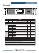
The following tables contain information on measured current consumption as well as calculated heat dissipation during normal operation
(1/8 rated power); and during extreme heavy duty operation (max power).
FP 10000Q
Level Load Rated power Line current *2) Watt *1) Thermal Dissipation
120 VAC 230 VAC In Out Dissipated BTU/hr kCal/hr
Standby, with remote power off via NomadLink®
0 0 0 0 0
Power On, Idling
139 0 139 475 120
Amp (l) Watt *1)
Pink pseudo
noise (1/8
rated power)
16 Ω / Ch. 660 x 4
10.7 5.6 732 330 402 1371 345
32 Ω / Bridged 1320 x 2
8 Ω / Ch. 1300 x 4
16.9 8.8 1224 650 574 1958 493
16 Ω / Bridged 2600 x 2
4 Ω / Ch. 2100 x 4
25.9 13.5 1914 1050 864 2949 74 3
8 Ω / Bridged 4200 x 2
2 Ω / Ch. *4) 2500 x 4
32.2 16.8 2414 1250 1164 3973 1001
4 Ω / Bridged *4) 5000 x 2
Pink pseudo
noise (max
power *3)
16 Ω / Ch. 660 x 4
13.6 7.1 1143 880 263 897 226
32 Ω / Bridged 1320 x 2
8 Ω / Ch. 1300 x 4
22.4 11.7 2096 1733 363 1238 312
16 Ω / Bridged 2600 x 2
4 Ω / Ch. 2100 x 4
30.0 16.0 2377 / 2455 1466 / 1542 910 / 914 3107 / 3118 783 716
8 Ω / Bridged 4200 x 2
2 Ω / Ch. *4) 2500 x 4
30.0 16.0 2237 / 2291 1099 / 1145 1139 / 114 6 3886 / 3911 979 / 985
4 Ω / Bridged *4) 5000 x 2
Mains connector, 230 V CE version
16 A, CEE7
Mains connector, 115 V ETL version
30 A, Twist Lock
*1) The amplifier section’s PSU operates as a non-resistive load, so the calculation “Volts x Amps = Watts” would not be correct. Instead, measured and
specified here is what is known as the “Active Power” of the amplifier section providing useful, real-world values of power consumption and heat dissipation.
*2) Current draw figures measured at 230 V. 115 V figures are converted from 230 V figures.
*3) Figures measured at maximum power before amplifier protection and limiter features are engaged. Typically this is between 1/4 and 1/3 of rated power.
Note that the maximum power condition is very extreme and will not occur during normal operation. Also note that the mains breaker will not be tripped
even if operation is in excess of maximum ratings.
*4) Italics used for conditions that, if sustained over long time periods, may trigger the mains breaker. Therefore these measurements should not be used
when calculating cooling requirements as they cannot be sustained by the mains breaker over time.
VHF
TEM
NOMAD
LINK
BRIDGE C+D
SIG -20 -15 -10 -4
VPL CPL
SIG -20 -15 -10 -4
VPL CPL
BRIDGE A+B
MUTE
MUTE
SIG -20 -15 -10 -4
VPL CPL
SIG -20 -15 -10 -4
VPL CPL
HI-IMP
HI-IMP
HI-IMP
HI-IMP
CLIP
CLIP
CLIP
CLIP
VHF
TEM
VHF
TEM
VHF
TEM
PWR
PAL
FP10000Q
-10dB
-inf
0
-10dB
-inf
0
-10dB
-inf
0
-10dB
-inf
0
channel
A
B
channel
C
channel
D
channel
FP SERIES
R
POW
POW