
Current Draw & Thermal Dissipation

Current Draw and Thermal Dissipation
FP+ Series: Dedicated Touring Amplifiers
FP 14000
WWW.LABGRUPPEN.COM
Item no. CDTD-FP14000 - 03.12.2015
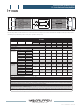
The following tables contain information on measured current consumption as well as calculated heat dissipation during normal operation
(1/8 rated power); and during extreme heavy duty operation (max power).
FP 14000
Level Load Rated power Line current *2) Watt *1) Thermal Dissipation
120 VAC 230 VAC In Out Dissipated BTU/hr kCal/hr
Standby, with remote power off via NomadLink® 0 0 0 0 0
Power On, Idling 129 0 129 440 111
Amp (l) Watt *1)
Pink pseudo
noise (1/8
rated power)
16 Ω / Ch. 1200 x 2
9.1 4.8 628 300 328 1118 282
32 Ω / Bridged 2400 x 1
8 Ω / Ch. 2350 x 2
14.8 7.7 1081 588 493 1683 424
16 Ω / Bridged 4700 x 1
4 Ω / Ch. 4400 x 2
23.9 12.5 1880 110 0 780 2661 670
8 Ω / Bridged 8800 x 1
2 Ω / Ch. *4) 7000 x 2
34.0 17. 8 2750 175 0 1000 3412 860
4 Ω / Bridged *4) 14000 x 1
Pink pseudo
noise (max
power) *3)
16 Ω / Ch. 1200 x 2
16.0 8.4 125 3 800 453 1546 390
32 Ω / Bridged 2400 x 1
8 Ω / Ch. 2350 x 2
30.0 16.0 2259 / 2409 1500 / 1600 759 / 809 2589 / 2762 652 / 696
16 Ω / Bridged 4700 x 1
4 Ω / Ch. 4400 x 2
30.0 16.0 2320 / 2474 1463 / 1560 857 / 914 2926 / 3121 737 / 786
8 Ω / Bridged 8800 x 1
2 Ω / Ch. *4) 7000 x 2
30.0 16.0 2277 / 2429 1266 / 1350 1012 / 1079 3453 / 3683 870 / 928
4 Ω / Bridged *4) 14000 x 1
Mains connector, 230 V CE version
16 A, CEE7
Mains connector, 115 V ETL version
30 A, Twist Lock
*1) The amplifier section’s PSU operates as a non-resistive load, so the calculation “Volts x Amps = Watts” would not be correct. Instead, measured and
specified here is what is known as the “Active Power” of the amplifier section providing useful, real-world values of power consumption and heat dissipation.
*2) Current draw figures measured at 230 V. 115 V figures are converted from 230 V figures.
*3) Figures measured at maximum power before amplifier protection and limiter features are engaged. Typically this is between 1/4 and 1/3 of rated power.
Note that the maximum power condition is very extreme and will not occur during normal operation. Also note that the mains breaker will not be tripped
even if operation is in excess of maximum ratings.
*4) Italics used for conditions that, if sustained over long time periods, may trigger the mains breaker. Therefore these measurements should not be used
when calculating cooling requirements as they cannot be sustained by the mains breaker over time.
-10dB
-inf
0
-10dB
-inf
0
B
channel
channel
A
FP SERIES
VHF
TEM
VHF
TEM
channel A
-20 -15 -10 -4
VPL CPL
channel B
-20 -15 -10 -4
VPL CPL
BRIDGE A+B
SIG
SIG
PWR
PAL
NOMAD
LINK
MUTE
MUTE
CLIP
CLIP
HI-IMP
HI-IMP
FP14000
R
POW
POW