
Instruction Manual


6. Fan grill filters
Two grilles with foam filters are located on the front panel to prevent dust from entering the amplifier. For
easy cleaning of the filters the grilles are removable by simply pulling them off. The foam filters should
always be used.
7. Power switch
Turns mains power on or off. (See page 10
and 14)
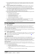
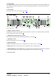
QKP= oÉ~ê=m~åÉä=
Figure 2. Rear Panel
1. Output / Speaker connector
The Speakon connector from Neutrik® may be unfamiliar to some users. A full description can be found
in the “Connections” section. (See page 13
)
2. Minimum load selector (MLS™) switch
This switch is used to select the maximum output power. (See page 9
)
3. Clip limiter switch
Turns the clip limiter on or off. (See page 15
)
4. Input signal XLR.
Neutrik® Combojack features also ¼” TRS phone jacks. (Pin 2 is “hot”, see page 12
)
5. Link switch. Allows a single input to drive channels B and C simultaneously.
7. Link and Polarity reverse switch. Allows a single input to drive channels A and B and/ or channels
C and D simultaneously. Also used for bridged operation of channel pairs (See page 7
).
9. AC power cable.
i~ÄKÖêìééÉå== = = = = ====================== ========================R
rëÉê=j~åì~ä===Ñm=OQMMnLNNR=====sÉêëáçå=MKT========OMMPJMOJOR=