
Owner's manual


7. Fan grill filters
A grille with foam filters is located on the front panel to prevent dust from entering the amplifier. The
grille is removable for easy cleaning of the filter by simply pulling them off. The foam filter should always
be used.
8. Carry/protection handle
Both handles can be used to carry the amplifier; they also act as protection for the front panel. In fixed
installations or where rack front covers are too shallow, they may be removed by unscrewing the
retaining bolts behind the front panel.
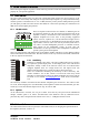
QKP= oÉ~ê=m~åÉä=
Figure 2. Rear Panel
1. Output / Speaker connector
The Speakon connector from Neutrik® may be unfamiliar to some users. A full description is found in the
connections section. (See page 12
).
3. Clip limiter switch
Turns the clip limiter on (switch IN position) or off (switch OUT position). (See page 13
).
4. Input signal XLR. Neutrik® Combojack features also ¼” TRS phone jacks. (Pin 2 is “hot”, see page
10
).
5. Link Output. 3-pole screw terminal of Phoenix brand. Connected in parallel to the female XLR
input connector for linking the channel to another input.
6. Gain switch channel B. Three of the switches in the DIP-switch selects the maximum gain of the
channel to be either 20, 23, 26, 29, 32, 35, 38 or 41 dB. (See page 6
).
7. Link/ Bridge switch. Two of the switches in the DIP-switch are used for Link and Bridge operation.
(See page 6
).
8. Gain switch channel A. Three of the switches in the DIP-switch selects the maximum gain of the
channel to be either 20, 23, 26, 29, 32, 35, 38 or 41 dB. (See page 6
).
9. AC power cable. WARNING!
A label just below the mains cable on the rear of the amplifier indicates the AC mains
voltage, for which the amplifier is wired. Connect the power cable only to the AC source
referred to on the label.
!
i~ÄKÖêìééÉå== = = = = = ========================R
rëÉê=j~åì~ä===ám=NPRM====sÉêëáçå=MKP======OMMPJMOJOR=