
User guide


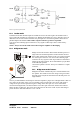

Table Of Contents

the amplifiers.
There are eight positions with different gain, from 20dB to 41dB in 3dB steps. See the different settings
for the DIP-switches in the table below. The three switches to the very left are for channel B, and the three
to the very right are for channel A.
RKNKO= pÉåëáíáîáíó=
Sensitivity is defined as how many volts (rms) or dBu (referred to 0.775Vrms)
are required to get full output power. As the output power varies with the load
impedance, usually 4 ohms is the reference. But in case of an MLS-switch
equipped amplifier there are enough choices for full output levels into
different load impedances for a sensitivity table to fill several pages.
Hence we recommend calculating the sensitivity if this is necessary. Our
”Audio calculator” can do this, which is an Excel file with many useful
formulas. It contains help for setting up digital loudspeaker processors and can
be found on our website www.labgruppen.com
: check in the ”Downloads”
area.
The sensitivity calculator is found in the box labeled “Amplifier gain
conversions”. The values to enter are in red; desired output power, load impedance and the selected
maximum gain. The sensitivity is in the box labeled “Input level for clip” in Vrms or dBu.
RKNKP= léíáçåë=
As the DIP-switch is recessed, one can put a sticker across the bay and prevent from unauthorized
changes. Another option is to remove the DIP-switch. This should be done by authorized service
personnel only! This corresponds to all switches set to “off”, i.e. 32dB gain and stereo mode.
RKO= iáåâ=ëïáíÅÜ=
The Link switch located on the rear panel (the central DIP-switch) is for changing the operation mode of
the amplifier (see below, section 5.3).
RKP= léÉê~íáçå=ãçÇÉë=
RKPKN= píÉêÉç=ãçÇÉ=
In this mode, both channels operate independently of each other. This is
used for all 2-channel modes, such as stereo and bi-amping. Set the two
center switches to off position for the stereo mode. The level attenuators
on the front panel will control the respective channels levels.
Never connect either output terminal to ground or in parallel. The
recommended minimum nominal impedance, for stereo or tandem
operation, is 2 ohms per channel.
RKPKO= kçíÉ=Ñçê=ÄÉåÅÜ=íÉëí=
NOTE: Channel B is always polarity reversed on the input, but polarity compensated by feeding the
minus pin on the Channel B output with the output voltage. Channel A output is connected in normal
polarity mode. By having channel A and B operating in opposite polarity, the energy storage in the
power supply is more efficient. This is significant for signals below 100 Hz (sub bass etc.) and improves
the power bandwidth. Be sure to use balanced inputs on all measurement equipment (also
oscilloscope probes) if you are bench testing.
i~ÄKÖêìééÉå== = = = = = ========================S
rëÉê=j~åì~ä===ám=QRM======sÉêëáçå=MKP========OMMPJMOJOR=