
Instruction Manual


3. Rear panel
IPD SERIES Operation Manual rev 1.0.0
9
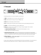
3. Rear panel
1 2
3 4
5
6
The following indicators and controls are available on the rear panel:
1 ANALOG INPUTS and LINK - XLR-F input connectors provided for each channel, with XLR-M link
output connectors.
2 AES3 INPUT and LINK - AES3 digital inputs are on an XLR-F connector with a link output on an
XLR-M connector.
3 NETWORK (Ethernet) - An RJ45 jack is supplied for connection to an Ethernet network for external control
and monitoring, either by a direct wired connection or via an external WiFi router to an iPad or tablet.
LEDs below the connector indicate valid network connection (LINK) and network activity (ACT).
When several IPDs are connected to a network, a switch with a built-in DHCP server should be used.
4 speakON OUTPUT CONNECTORS - Both channel outputs are available on a four-pole connector at the left;
either channel 1 or both channels 1 and 2 may be connected. Only channel 2 is available on the connector to
the right.
5 BINDING POST CONNECTORS - Connectors for channel 1 and channel 2.
6 AC LINE INPUT - A locking IEC receptacle accepts the AC line input at 50 Hz or 60 Hz, 100 V - 240 V.
Use an IEC cable with the proper connector for country of use.