
Operation Manual


4. Signal flow block diagram
10
IPD SERIES Operation Manual rev 2.0.0
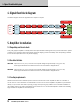
4. Signal flow block diagram
The below diagram shows the signal ow from inputs to outputs:
Analog 1
Analog 2
AES 1
AES 2
Input 1
Levels
Input 1
EQ
Input 1
delay
Output 1
Levels
Output 1
EQ
IDEEA
Amplifier
Output 1
Delay
Clip Limiter
Clip Limiter
Rail Sense Limiter
SCVPLX-Over
Input 2
Levels
Input 2
EQ
Input 2
delay
Output 2
Levels
Output 2
EQ
IDEEA
Amplifier
PSU
Output 2
Delay
SCVPLX-Over
Input
Mixer
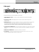
5. Amplifier installation
5.1. Unpacking and visual check
Every Lab.gruppen amplier is carefully tested and inspected before leaving the factory and should arrive in perfect
condition. If any damage is discovered, please notify the shipping carrier immediately. Save the packing materials
for the carrier’s inspection and for any future shipping.
5.2. Rack installation
IPD 1200 - Depth is 272 mm (10.7”) rack ear to back panel. Weight is approximately 4.6 kg (10.1 lbs).
Rear support brackets are included and use is recommended in all applications.
IPD 2400 - Depth is 360 mm (14.2”) rack ear to back panel. Weight is approximately 6.2 kg (13.7 lbs).
Rear support brackets are included and use is recommended in all applications.
5.3. Cooling requirements
Please ensure that there is sufcient space in the front and the rear of each amplier to allow for a free ow of
air. No doors or covers should be mounted either in the front or rear of the ampliers. Ampliers may be stacked
directly on top of each other with no spacing, though some spacing may enable more convenient installation of
rear cabling. Refer to the Thermal Dissipation charts in Section 15.2 for thermal dissipation values when installing
large numbers of ampliers in enclosed spaces.